Download
1 / 11
110 likes | 124 Views
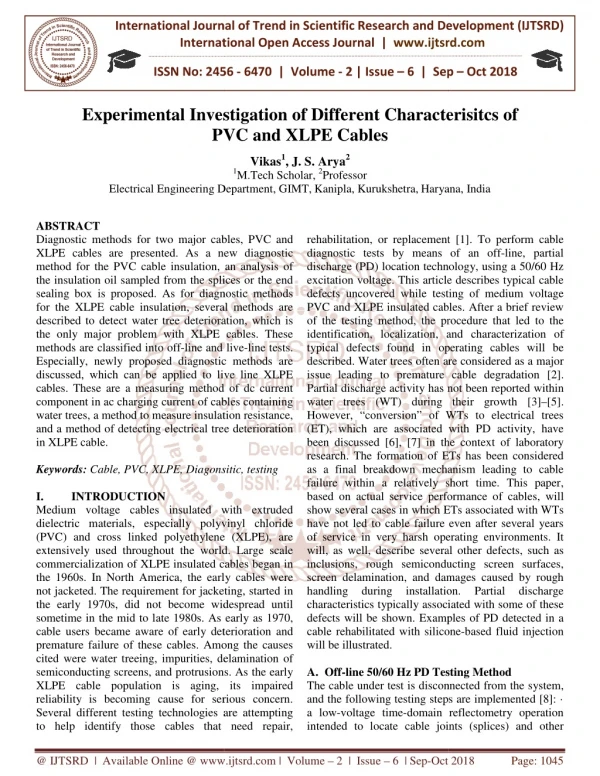
Diagnostic methods for two major cables, PVC and XLPE cables are presented. As a new diagnostic method for the PVC cable insulation, an analysis of the insulation oil sampled from the splices or the end sealing box is proposed. As for diagnostic methods for the XLPE cable insulation, several methods are described to detect water tree deterioration, which is the only major problem with XLPE cables. These methods are classified into off line and live line tests. Especially, newly proposed diagnostic methods are discussed, which can be applied to live line XLPE cables. These are a measuring method of dc current component in ac charging current of cables containing water trees, a method to measure insulation resistance, and a method of detecting electrical tree deterioration in XLPE cable. Vikas | J. S. Arya "Experimental Investigation of Different Characterisitcs of PVC and XLPE Cables" Published in International Journal of Trend in Scientific Research and Development (ijtsrd), ISSN: 2456-6470, Volume-2 | Issue-6 , October 2018, URL: https://www.ijtsrd.com/papers/ijtsrd18830.pdf Paper URL: http://www.ijtsrd.com/engineering/electrical-engineering/18830/experimental-investigation-of-different-characterisitcs-of-pvc-and-xlpe-cables/vikas<br>

E N D
International Journal of T International Open Access Journal International Open Access Journal | www.ijtsrd.com International Journal of Trend in Scientific Research and Development (IJTSRD) Research and Development (IJTSRD) www.ijtsrd.com ISSN No: 2456 ISSN No: 2456 - 6470 | Volume - 2 | Issue – 6 | Sep 6 | Sep – Oct 2018 Experimental Investigation Experimental Investigation of Different Characterisitcs of PVC and XLPE Cables of Different Characterisitcs of PVC Vikas1, J. S. Arya2 1M.Tech Scholar, 2Professor Electrical Engineering Department Electrical Engineering Department, GIMT,Kanipla, Kurukshetra,Haryana Haryana, India ABSTRACT Diagnostic methods for two major cab XLPE cables are presented. As a new diagnostic method for the PVC cable insulation, an analysis of the insulation oil sampled from the splices or the end sealing box is proposed. As for diagnostic methods for the XLPE cable insulation, several described to detect water tree deterioration, which is the only major problem with XLPE cables. These methods are classified into off-line and live Especially, newly proposed diagnostic methods are discussed, which can be applied to live cables. These are a measuring method of dc current component in ac charging current of cables containing water trees, a method to measure insulation resistance, and a method of detecting electrical tree deterioration in XLPE cable. Keywords: Cable, PVC, XLPE, Diagonsitic, testing I. INTRODUCTION Medium voltage cables insulated with extruded dielectric materials, especially polyvinyl chloride (PVC) and cross linked polyethylene (XLPE), are extensively used throughout the world. Large scale commercialization of XLPE insulated cables began in the 1960s. In North America, the early cables were not jacketed. The requirement for jacketing, started in the early 1970s, did not become widespread until sometime in the mid to late 1980s. As early as 197 cable users became aware of early deterioration and premature failure of these cables. Among the causes cited were water treeing, impurities, delamination of semiconducting screens, and protrusions. As the early XLPE cable population is aging, its impai reliability is becoming cause for serious concern. Several different testing technologies are attempting to help identify those cables that need repair, to help identify those cables that need repair, rehabilitation, or replacement [1]. To perform cable diagnostic tests by means of an off discharge (PD) location technology, using a 50/60 Hz excitation voltage. This article describes typical cable defects uncovered while testing of medium voltage PVC and XLPE insulated cables. After a brief review of the testing method, the procedure t identification, localization, and characterization of typical defects found in operating cables will be described. Water trees often are considered as a major issue leading to premature cable degradation [2]. Partial discharge activity has n water trees (WT) during their growth [3] However, “conversion” of WTs to electrical trees (ET), which are associated with PD activity, have been discussed [6], [7] in the context of laboratory research. The formation of ETs has as a final breakdown mechanism leading to cable failure within a relatively short time. This paper, based on actual service performance of cables, will show several cases in which ETs associated with WTs have not led to cable failure even of service in very harsh operating environments. It will, as well, describe several other defects, such as inclusions, rough semiconducting screen surfaces, screen delamination, and damages caused by rough handling during installation. characteristics typically associated with some of these defects will be shown. Examples of PD detected in a cable rehabilitated with silicone will be illustrated. A.Off-line 50/60 Hz PD Testing Method The cable under test is disconnected from the system, and the following testing steps are implemented [8]: · a low-voltage time-domain reflectometry operation intended to locate cable joints (splices) and other intended to locate cable joints (splices) and other Diagnostic methods for two major cables, PVC and XLPE cables are presented. As a new diagnostic method for the PVC cable insulation, an analysis of the insulation oil sampled from the splices or the end sealing box is proposed. As for diagnostic methods for the XLPE cable insulation, several methods are described to detect water tree deterioration, which is the only major problem with XLPE cables. These rehabilitation, or replacement [1]. To perform cable diagnostic tests by means of an off-line, partial discharge (PD) location technology, using a 50/60 Hz excitation voltage. This article describes typical cable defects uncovered while testing of medium voltage PVC and XLPE insulated cables. After a brief review of the testing method, the procedure that led to the identification, localization, and characterization of typical defects found in operating cables will be described. Water trees often are considered as a major issue leading to premature cable degradation [2]. Partial discharge activity has not been reported within water trees (WT) during their growth [3]–[5]. However, “conversion” of WTs to electrical trees (ET), which are associated with PD activity, have been discussed [6], [7] in the context of laboratory research. The formation of ETs has been considered as a final breakdown mechanism leading to cable failure within a relatively short time. This paper, based on actual service performance of cables, will show several cases in which ETs associated with WTs have not led to cable failure even after several years of service in very harsh operating environments. It will, as well, describe several other defects, such as inclusions, rough semiconducting screen surfaces, screen delamination, and damages caused by rough handling during installation. characteristics typically associated with some of these defects will be shown. Examples of PD detected in a cable rehabilitated with silicone-based fluid injection line and live-line tests. Especially, newly proposed diagnostic methods are o live line XLPE cables. These are a measuring method of dc current component in ac charging current of cables containing water trees, a method to measure insulation resistance, and a method of detecting electrical tree deterioration Cable, PVC, XLPE, Diagonsitic, testing Medium voltage cables insulated with extruded dielectric materials, especially polyvinyl chloride linked polyethylene (XLPE), are extensively used throughout the world. Large scale mmercialization of XLPE insulated cables began in the 1960s. In North America, the early cables were not jacketed. The requirement for jacketing, started in the early 1970s, did not become widespread until sometime in the mid to late 1980s. As early as 1970, cable users became aware of early deterioration and premature failure of these cables. Among the causes cited were water treeing, impurities, delamination of semiconducting screens, and protrusions. As the early XLPE cable population is aging, its impaired reliability is becoming cause for serious concern. Several different testing technologies are attempting Partial discharge line 50/60 Hz PD Testing Method test is disconnected from the system, and the following testing steps are implemented [8]: · domain reflectometry operation @ IJTSRD | Available Online @ www.ijtsrd.com www.ijtsrd.com | Volume – 2 | Issue – 6 | Sep-Oct 2018 Oct 2018 Page: 1045
International Journal of Trend in Scientific Research and Development (IJTSRD) ISSN: 2456-6470 irregularities, such as corroded neutrals; · a sensitivity assessment test; · a PD magnitude calibration test; · a PD detection and location test under voltage stress conditions; · data analysis and reporting; and · a “matching” test to locate the exact physical PD site in a buried cable. Each of these steps, except the first— which has no direct relevance to the subject of this paper—will be briefly described. 1.Sensitivity Assessment The purpose of this step is to determine the value in picoCoulomb (pC) of the smallest PD signal detectable under the test conditions. The setup is illustrated in Figure 1. A calibrated pulse, such as 5 pC, is injected at the near end. The PD estimator detects and records the response. If the reflected signal cannot be seen above the filtered noise level, a larger signal, such as 10 pC, is injected. This process is repeated until the reflected signal is observable. This determines the smallest PD signal that can be resolved under the test conditions. 2.PD Magnitude Calibration The calibrated pulse generator is connected to the cable remote end. A large signal, such as 50 pC or 100 pC, is injected. The corresponding signal recorded at the near end is evaluated by integrating it with respect to time (q = k????). The constant k is adjusted until the PD magnitude read is 50 pC or 100 pC. The instrument is now calibrated for measuring the apparent charge, q, of the PD. 3.PD Testing under Voltage Stress In Figure 1, the pulse generator is replaced by a 50/60 Hz resonant transformer. The voltage is rapidly raised to the cable operating level (1.0p.u.) at which it is maintained for several minutes as a conditioning step. The voltage is ramped to its maximum value (such as 2.0p.u. or 2.5p.u.). It then is returned to zero as quickly as possible. During this stress cycle, several sets of data are captured, as shown in Figure 2, each set encompasses an entire 50/60 Hz period. The rising and falling parts of the voltage help determine the PD inception voltage (PDIV) and extinction voltage (PDEV), respectively. Figure1. Setup to assess the threshold of sensitivity during a field test Figure2. Time profile of the excitation voltage applied during a partial discharge (PD) test 4.Data Analysis and Reporting Figure 3 illustrates a typical data set. Prior to analysis, noise mitigation filters are applied. A cursor moving from left to right stops at each signal whose magnitude exceeds a preset value dictated by the remaining background noise, and displays the signal in a time-expanded frame. The PD magnitude, the phase angle at which it occurred, and its location estimated by reflectometry are determined and stored. Figure 4 is a histogram showing the frequency of PD occurrence per cycle versus the PD location at each voltage level. For each PD, a phase-resolved display is prepared at each test voltage level, as will be shown later. Figure3. Unprocessed partial discharge (PD) data (above) recorded during one voltage cycle and data after noise mitigation (below). @ IJTSRD | Available Online @ www.ijtsrd.com | Volume – 2 | Issue – 6 | Sep-Oct 2018 Page: 1046
International Journal of Trend in Scientific Research and Development (IJTSRD) ISSN: 2456-6470 5.“Matching” Operation The purpose of this operation is to match the estimated PD site to its actual physical location along a buried cable. The Characterization of Cable Defects A. Procedure In order to identify the PD causing defect, a cable section of a minimum 7 m length— containing the “matched” PD site—is removed from the field and subjected to a laboratory investigation where a final PD location is carefully performed from both cable ends, using the regular reflectometry method or an accurate “time -of-arrival” method. A large number of measurements have confirmed that the PD site located in the field and that found in the laboratory are generally within ±0.6 m of each other. The cable is sectioned into 0.3 m long specimens; one contains the measured PD site and the rest cover 0.9 m length on either side of the PD site. The protective jacket, the concentric neutrals (or metal shields), and the insulation screen are removed. A thorough visual examination of the insulation surface can often reveal the exact location of the PD site. The specimens are immersed in a bath of silicone oil heated to approximately 110°C, until the XLPE insulation becomes transparent. Visual examination of the insulation reveals the defect, which is properly marked. After cooling, the insulation is machined into a 0.25 mm –0.50 mm thick spiral (slinky) for microscopic examination. Generally, the examination is done without applying a dye. However, dyeing with a solution of methylene blue is an option that is sometimes exercised to confirm the existence of a WT. B. Electrical Trees Associated with Water Trees Water treeing manifests itself as strings of water-filled micro cavities. Relative to dry XLPE, the insulation containing WTs has a higher permittivity (dielectric constant) and a higher conductivity. Whether the WT is of the vented (growing out of one of the screens) or bowtie (growing from the insulation volume radially toward both screens) variety, its share of the total voltage applied across the insulation is very small compared to the dry insulation surrounding it. As a result, ETs tend to form in the dry areas adjacent to WTs whenever defective sites with enhanced electric stress exist in these areas. Discernible PD may not be sustained within the WT, but it does occur at the surrounding ET sites. Several examples follow. Electrical Tree Growing from Screen toward Vented WT: Figure 4 illustrates a large, vented WT emanating from a conductor screen and an ET emanating from the insulation screen. Figure 4 Vented water tree (WT) and electrical tree (ET) growing into each other from opposite screens. II. CABLE STANDARDS AND TESTS Bureau of Indian Standards (BIS) is the national Standards Body of India working under the aegis of Ministry of Consumer Affairs, Food & Public Distribution, Government of India. It is established by the Bureau of Indian Standards Act, 1986 which came into effect on 23rd December 1986. The Minister in charge of the Ministry or Department having administrative control of the BIS is the ex-officio President of the BIS. The organization was formerly the Indian Standards Institution (ISI), set up under the Resolution of the then Department of Industries and Supplies No. 1 Std.(4)/45, dated 3 September 1946. The ISI was registered under the Societies Registration Act, 1860. As a corporate body, it has 25 members drawn from Central or State Governments, industry, scientific and research institutions, and consumer organizations. Its headquarters are in New Delhi, with regional offices in Kolkata, Chennai, Mumbai, Chandigarh and Delhi and 20 branch offices. It also works as WTO- TBT enquiry point for India. Cable certifications is to be obtained voluntarily from BI because these cables are concerned with the safety of the consumers. This Indian Standard is proposed to be adopted by the Bureau of Indian Standard after the draft finalized by the Power Cable Sectional Committee was approved by the Electro technical Division Council. In the formulation of this standard, assistance is derived from the following standards: @ IJTSRD | Available Online @ www.ijtsrd.com | Volume – 2 | Issue – 6 | Sep-Oct 2018 Page: 1047
International Journal of Trend in Scientific Research a International Journal of Trend in Scientific Research and Development (IJTSRD) ISSN: 2456 nd Development (IJTSRD) ISSN: 2456-6470 A.HALOGEN FREE FLAME RETARDANT (HFFR) CABLES FOR WORKING VOLTAGES UPTO AND INCLUDING 1100 VOLTS – Table1. Halogen Free Flame Retardant (Hffr) Cables Flame Retardant (Hffr) Cables for Working Voltages Up to Volts –Specification HALOGEN FREE FLAME RETARDANT (HFFR) CABLES FOR WORKING VOLTAGES UPTO HALOGEN FREE FLAME RETARDANT (HFFR) CABLES FOR WORKING VOLTAGES UPTO –SPECIFICATION to and Including 1100 IS / IEC / BS /BSEN Pub. Title PVC insulated unsheathed and sheathed cables / cords with rigid and flexible PVC insulated unsheathed and sheathed cables / cords with rigid and flexible PVC insulated unsheathed and sheathed cables / cords with rigid and flexible conductor for working voltage up conductor for working voltage up to and including 1100 V with amendments to and including 1100 V with amendments IS 694 : 2010 IEC 60227 part 1 to 5 PVC insulated cables of rated voltages up to and including 450 PVC insulated cables of rated voltages up to and including 450 PVC insulated cables of rated voltages up to and including 450/750V IEC 60228 ( 2004-11) Conductors of insulated cables Conductors of insulated cables BS 6500 : 1984 Insulated flexible cords and cables Insulated flexible cords and cables BS EN 50363 – 7 :2005 Halogen Free, thermoplastic, insulating compound Insulating materials for shipboard and off shore units, po instrumentation, telecommunication and data cables instrumentation, telecommunication and data cables Halogen Free, thermoplastic, insulating compound Insulating materials for shipboard and off shore units, po wer, Control, IEC 60092-351 BS EN 50363-8:2005 Halogen free, thermoplastic, sheathing compound Electric Cable including 450/750V Determination of degree of acidity of gases for materials by Measuring pH and conductivity Thermoplastic sheathing compounds having low emission of Corrosive gases and suitable for use in cables having low Emission of smoke whe fire Cross linked sheathing compounds having low emission of Corrosive gases and suitable for use in cables having low Emission of smoke when affected by fire suitable for use in cables having low Emission of smoke when affected by fire suitable for use in cables having low Emission of smoke when affected by fire Halogen free, thermoplastic, sheathing compound Electric Cable – Low voltage energy cables of rated voltages Up To and including 450/750V- Part 1 Determination of degree of acidity of gases for materials by Measuring pH and conductivity Thermoplastic sheathing compounds having low emission of Corrosive gases and suitable for use in cables having low Emission of smoke whe and suitable for use in cables having low Emission of smoke when affected by Low voltage energy cables of rated voltages Up To and BS EN 50525-1:2011 Determination of degree of acidity of gases for materials by Measuring pH and BS EN 50267-2 Thermoplastic sheathing compounds having low emission of Corrosive gases BS 7655- part 6.1 linked sheathing compounds having low emission of Corrosive gases and linked sheathing compounds having low emission of Corrosive gases and BS 7655- part 8 IEC 60684 -2 Flexible insulation sleeving Flexible insulation sleeving – Test method For the purpose of deciding whether a particular requirement of this standard is complied with, the final value, observed value, or calculated value expressing the result of a test shall be rounded off in accordance with IS 2-1960*. The number of significant places retained in the rounded off value should be the same as that of the specified value in this standard. This specification covers general requirements of single and multi core cables / cords with rigid as well as flexible annealed bare/tinned copper and alu conductor insulated and sheathed (if any) with Thermoplastic or Cross linked Halogen Free Flame Retardant (HFFR) material for voltages up to and including 1100 volts AC, 50 Hz, used in power and lighting installations including cables for low temperature applications. These cables may be used on DC systems for rated voltages up to and including 1500 volts to earth. These cables are suitable to use for conductor temperature not exceeding 70O C for thermoplastic or 90°C for cross linked material. thermoplastic or 90°C for cross linked material. purpose of deciding whether a particular requirement of this standard is complied with, the final value, observed value, or calculated value expressing the result of a test shall be rounded off in 1960*. The number of s retained in the rounded off value should be the same as that of the specified value in NOTES 1.The term cord is used for the flexible cables up to 5 cores covering sizes up to 2.5 Sq.mm. 2.Cables covered in this standard are suitable for indoor use only. 3.The following types of cables are not covered in this standard. They are a) Telephone cables, Data transmission cables, c) Instrumentation cables and d) Screened communication cables. 4.The test specified in section 1, 2 and 3 of this specification shall meet the requirements specified in IS 8130 : 2013 for conductors, Annex 1 & 2 for HFFR insulation and sheath are tested as per the test methods given in relevant parts of IS 10810 and those specifically specification. 5.This standard covers the following categories of cables. Category code Cable description a.Thermoplastic 700C b.Thermoplastic 90OC ( Sheath only ) c.Cross linked 70OC 04 Cross C 04 Cross linked 90OC. The term cord is used for the flexible cables up to 5 cores covering sizes up to 2.5 Sq.mm. Cables covered in this standard are suitable for The following types of cables are not covered in this standard. They are a) Telephone cables, b) Data transmission cables, c) Instrumentation cables and d) Screened communication cables. The test specified in section 1, 2 and 3 of this specification shall meet the requirements specified in IS 8130 : 2013 for conductors, Annex 1 & 2 for ion and sheath are tested as per the test methods given in relevant parts of IS 10810 and those specifically This specification covers general requirements of core cables / cords with rigid as well as flexible annealed bare/tinned copper and aluminum conductor insulated and sheathed (if any) with Thermoplastic or Cross linked Halogen Free Flame Retardant (HFFR) material for voltages up to and 50 Hz, used in power and lighting installations including cables for low ature applications. These cables may be used on DC systems for rated voltages up to and including 1500 volts to earth. These cables are suitable to use for conductor temperature not exceeding 70O C for specified specified in in this this This standard covers the following categories of cables. Category code Cable description C ( Sheath only ) @ IJTSRD | Available Online @ www.ijtsrd.com w.ijtsrd.com | Volume – 2 | Issue – 6 | Sep-Oct 2018 Oct 2018 Page: 1048
International Journal of Trend in Scientific Research and Development (IJTSRD) ISSN: 2456-6470 6.This specification is divided into the following three sections : Section –1: General Requirements Section– 2: Unsheathed Single core cables/cords for fixed and flexible wiring Section– 3: Sheathed/ Unsheathed single and multi- core cables/cords for fixed and flexible wiring. Table4.2. Indian Standards for cables and their description IS 1885 (Part32) 1971 Electro-technical Vocabulary: part 32 cables, conductors and Accessories for electricity supply IS 4905 : 1968 Methods for random sampling IS 8130 : 2013 Specification for conductors for Insulated electric cables and Flexible cords IS10810 – Methods of test for cables (Part 0) : 1984 General (Part 1) : 1984 Annealing test for wires used in conductors (Part 2) : 1984 Tensile test of Aluminum Wires (Part 3) : 1984 Wrapping test for aluminum wires (Part 4) : 1984 Persulphate test for tinned copper (Part 5) : 1984 Conductor Resistance test (Part 6) : 1984 Thickness of insulation and sheath (Part 7) : 1984 Tensile strength and elongation (Part 11) : 1984 Ageing test (Part 12) : 1984 Shrinkage test (Part 13) : 1984 Ozone resistant test (Part 15) : 1984 Hot deformation test (Part 20) : 1984 Cold bend test (Part 21) : 1984 Cold impact Test (Part 30) :1984 Hot set test (Part 43) : 1984 Insulation resistance test (Part 44) : 1984 Spark test (Part 45) : 1984 High Voltage Test (Part 53) : 1984 Flammability Test (Part 58) : 1998 Limited Oxygen index Test (Part 59) : 1988 HCL Emission Test (Part 61) : 1988 Flame Retardant Test (Part 62) : 1993 Flame Retardant Test for bunched cable (Part 63) : 1993 Smoke density test (Part 64) : 2003 Temperature index Test The standards listed below contain provisions which through reference in this text, constitute provisions of this standard. At the time of publication, the editions indicated were valid. All standards are subject to revision and parties to agreements based on this standard are encouraged to investigate the possibility of applying the most recent editions of the standards listed below: Title @ IJTSRD | Available Online @ www.ijtsrd.com | Volume – 2 | Issue – 6 | Sep-Oct 2018 Page: 1049
International Journal of Trend in Scientific Research a International Journal of Trend in Scientific Research and Development (IJTSRD) ISSN: 2456 nd Development (IJTSRD) ISSN: 2456-6470 B.TERMINOLOGY For the purpose of this standard, the definitions given in IS1885 (Part 32): 1971 and IS 10810 (Part 0 shall apply further to the following. 4.2.1 Rated voltage Rated voltage U0 being the r. m. s Voltage between any insulated conductor and earth. Rated Voltage U being the r. m. s Voltage between any two conductors of multi core cable. 4.2.1. Definitions related to insulated and sheathing material 4.2.1.1. Halogen Free Flame Retardant compound (HFFR) Combination of materials proportioned and treated of which characteristics constituent is the halogen free flame retardant plastomer or one of its co-polymers. The same term also designates compounds containing halogen free flame retardant polymers and some of its co polymers. 4.2.1.2. Type of compounds the category namely Thermoplastic or Thermo set (Cross linked compound is placed according to its properties, as determined by specific tests. 4.2.2. Routine Tests Tests made by manufacturer on all finished cable lengths to demonstrate the integrity of the cable. 4.2.3 Acceptance Tests Tests carried out on sample taken from a lot for the purpose of acceptance of the lot. 4.2.4. Type Tests Test required to be made before supplying a type of cable covered by this standard on a general commercial basis in order to demonstrate satisfactory performance characteristics to meet the intended applications. These tests are of such a natur they have been made, they need not be repeated unless changes are made in the cable materials or design or manufacturing process, which might change the performance characteristics. 4.2.5. Nominal Value The value by which a quantity is desi which is often used in tables. Usually in this standard, nominal values give rise to values to be checked by nominal values give rise to values to be checked by measurements taking in to account specified measurements taking in to account specified tolerances. 4.3. MATERIAL 4.3.1 Conductor 4.3.1.1 Material A. The conductors shall be compo Bare or tinned of high conductivity copper wires or Aluminium complying to IS B. A separator tape made of suitable Halogen free material applied over conductor at the discretion of the manufacturer. C. Electrical resistance – The resistance of conductor at 20°C per Km shall be in accordance with the requirements specified in relevant tables of IS 8130 : 2013 for the given class of conductor and tested as per IS 10810 part 5. D. The classes of the conductors relevant to the various types of cables are given in respective sections of this specification Section 3. E. Conductors of cables for fixed installation shall be circular solid or circular stranded or compacted circular or stranded sector shaped. F. Nominal cross sectional area of conductor of cables covered in this standard are given in respective tables. 4.3.2 Insulation 4.3.2.1. The insulation shall be either Thermoplastic or Cross linked halogen free flame retardant (HFFR) compound conforming to the requirements specified in Annex 1 of this specification. Type HFI (Thermoplastic) with rated temperature of 70°C and Type HFI- XL 70 / HFI- XL 90 Cross linked ( set) with rated temperature of 70 o C /90°C 4.3.2.2 Application to the conduc The insulation shall be so applied that it fits closely on the conductor. It shall be possible to remove it without damage to the insulation itself, to the conductor or to the tin coating if any. Compliance shall be checked by inspection and by Visual Inspection. 4.3.2.3 Thickness The mean value of the thickness of insulation shall be not less than the specified nominal value for each type and size of cable shown in the relevant tables given in Section 2 and 3 of this specification. The smallest of the measured values of thickness of insulation (ti) shall not fall below the nominal value (ti) specified in the relevant table by more than (0.1 mm +0.1 ti). the relevant table by more than (0.1 mm +0.1 ti). For the purpose of this standard, the definitions given 1971 and IS 10810 (Part 0): 1984 s Voltage between The conductors shall be composed of annealed Bare or tinned of high conductivity copper wires or Aluminium complying to IS 8130: 2013 A separator tape made of suitable Halogen free material applied over conductor at the discretion any insulated conductor and earth. Rated Voltage U s Voltage between any two-phase Definitions related to insulated and sheathing The resistance of conductor Halogen Free Flame Retardant compound at 20°C per Km shall be in accordance with the requirements specified in relevant tables of IS 8130 : 2013 for the given class of conductor and tested as per IS 10810 part 5. The classes of the conductors relevant to the ious types of cables are given in respective sections of this specification namely Section 2 and Combination proportioned and treated of which characteristics constituent is the halogen free flame retardant of materials suitably suitably selected, selected, polymers. The same term ompounds containing halogen free flame retardant polymers and some of its co- Conductors of cables for fixed installation shall be circular solid or circular stranded or compacted circular or stranded sector shaped. minal cross sectional area of conductor of cables covered in this standard are given in category namely Cross linked) in which compound is placed according to its properties, as The insulation shall be either Thermoplastic or Cross linked halogen free flame retardant (HFFR) Tests made by manufacturer on all finished cable lengths to demonstrate the integrity of the cable. he requirements specified in Annex 1 of this specification. Type HFI -TP 70 (Thermoplastic) with rated temperature of 70°C and XL 90 Cross linked (Thermo ) with rated temperature of 70 o C /90°C Tests carried out on sample taken from a lot for the Application to the conductor The insulation shall be so applied that it fits closely on the conductor. It shall be possible to remove it without damage to the insulation itself, to the conductor or to the tin coating if any. Compliance shall be checked by Inspection. Test required to be made before supplying a type of cable covered by this standard on a general commercial basis in order to demonstrate satisfactory performance characteristics to meet the intended applications. These tests are of such a nature that after they have been made, they need not be repeated unless changes are made in the cable materials or design or manufacturing process, which might change The mean value of the thickness of insulation shall be not less than the specified nominal value for each type and size of cable shown in the relevant tables given in Section 2 and 3 of this specification. The smallest of he measured values of thickness of insulation (ti) shall not fall below the nominal value (ti) specified in The value by which a quantity is designated and which is often used in tables. Usually in this standard, @ IJTSRD | Available Online @ www.ijtsrd.com w.ijtsrd.com | Volume – 2 | Issue – 6 | Sep-Oct 2018 Oct 2018 Page: 1050
International Journal of Trend in Scientific Research and Development (IJTSRD) ISSN: 2456-6470 4.3.2.4 Mechanical properties before and after ageing The insulation shall have adequate mechanical strength and elasticity within the temperature limits to which it may be exposed in normal use. The compliance shall be checked by carrying out tensile strength and elongation test, for respective type of compound, as per method given in IS 10810-Part 7. The applicable test values shall be obtained from Annex 1, for appropriate type of compound. 4.3.3. Fillers 4.3.3.1 The fillers, if provided, shall be of Halogen Free Flame Retardant Material. 4.3.3.2 The filler materials shall be suitable for operating temperature of the cable and compatible with other components of the cable. This shall not be harder than the HFFR material used for insulation and sheath. 4.3.4 Binder Tape Binder tape if required, shall also be of suitable material of halogen free in nature. 4.3.5 Sheath 4.3.5.1 The sheath shall consist of Halogen Free Flame Retardant Compound conforming to the requirements of HFS-TP 70 or HFS-TP 90 or HFS – XL 70 or HFS- XL 90 given in annex 2 of this specification. Notes: 1.Insulation and sheath material shall be compatible with each other as per the temperature rating of the cable. 2.A combination of cross linked insulation and thermoplastic sheath is also permissible 4.3.5.2 Application The sheath shall be applied in a single layer: A.On the core, in the case of single-core cables; B.On the assembly of cores and fillers or inner covering, if any, in the case of other cables. The sheath shall not adhere to the cores. A separator, consisting of a film or tape, or talcum powder may be placed under the sheath. This separator shall be compatible with the insulation and sheath materials. 4.3.5.3 Thickness The mean value of the thickness of sheath shall not be less than the specified nominal value for each type and size of cable shown in the tables of the particular specifications (Section 3 of this specification). However, the thickness of sheath determined by taking average of number of measurements shall be not less than nominal value (ts) specified in relevant Tables and smallest of the measured value shall not fall below the nominal value (ts) specified by more than 0.15 ts + 0.1 mm for Single Core Cables and 0.2 ts. + 0.2 mm. For Multi core cables. Compliance shall be checked by testing the dimensional requirements specified in section 2 & 3 and as per test method given in IS 10810 (Part 6): 1984 4.3.5.4 Mechanical properties before and after ageing The sheath shall have adequate mechanical strength and elasticity within the temperature limits to which it may be exposed in normal use. The compliance shall be checked by carrying out tensile strength and elongation test, shall meet the requirements given in Annex 2. 4.3.5.5 Overall dimensions The maximum overall dimensions of the cables shall be within the limits specified in the tables 3 to 8 given in Section 2 & 3 of this specification. 4.3.5.5.1 Ovality The difference between maximum and minimum measured values of overall diameter of sheathed circular cables shall not exceed 15 percent of the maximum measured value at the same cross section. 4.3.5.6 Color of sheath The color of sheath shall be black or in any color as agreed to between the purchaser and the supplier. 4.4. TESTS The testing on the cables will be conducted as given Table 4.2. For each category of cables listed under scope of this standard. Unless otherwise stated, the tests shall be carried out in accordance with appropriate part of IS 10810, taking into account the additional information given in this standard. 4.4.1. High Voltage Temperatures) (Acceptance and Routine Test) In case of multi core cables and cords test voltage shall be applied for a period of 5 minutes between the cores. Single-core cables shall be immersed in water at ambient temperature one hour before the testing Test, (at Room. @ IJTSRD | Available Online @ www.ijtsrd.com | Volume – 2 | Issue – 6 | Sep-Oct 2018 Page: 1051
International Journal of Trend in Scientific Research and Development (IJTSRD) ISSN: 2456-6470 4.4.8 Determination of Elements of halogen presents This test is done to determine the elements of halogen present and sequential test programme as given in table 4.1 of Annex.4. The detailed step by step sample testing sequence to table 4.2 of Annex 4. 4.4.9. Degree of acidity of combustion gases This test is done to determine the degree of acidity of combustion gasses for materials by measuring pH and conductivity. For details refer annex 6. 4.4.10 Toxicity index test – Under consideration 4.4.11 Flex Test – Under consideration 4.4.12 Persulphate Test The Tinned copper used in conductor shall meet the requirement as specified in IS 8130 and test conducted as per IS 10810 – 4.4.13 Flame retardant test The test shall be conducted as per IS 10810 (Part 61) on single core cable and after the test, there should be no visible damages on the test specimen within 300 mm from its upper end. 4.4.14 Hot set Test The insulation of heat resistance cross linked HFFR (HFI-XL70,HFI-XL 90,HFSXL70, HFS XL 90) cable are subjected to Hot set test and the elongation percent under load shall be maximum 175 percent and Permanent set shall be maximum 15 percent and tested as per IS 10810 – 30 4.4.15 Water Immersion Test (Effect of water on Sheath): This test represents the influence of water on the mechanical properties of sheath through tensile strength and elongation at break on untreated and treated samples after water immersion. The test results on the conditioned and unconditioned samples shall not have any significant change. The test samples are immersed into the de-ionized water for the temperature and duration as specified in 7 of Annex 2. After the water immersion the sample shall be cooled off to 20±5°C before taken out of water. The test samples are removed off the moisture using Tissue paper and the tensile strength and elongation at break tests are conducted within 40 minutes as IS 10810-7. and the test voltage shall be applied between conductor and water. For the specified period Cables / cords tested as above shall withstand without breakdown an ac voltage of 3 kV (rms) or a dc voltage of 7.5 kV for 5 minutes. 4.4.2 Spark Test (Routine Test) Spark test may be carried out as an alternate to high voltage on single core unsheathed cables. The voltage shall be as specified below: Thickness of Insulation(mm) Up to and including 1.0 Above 1.0 and up to and including 1.5 Above 1.5 and up to and including 2.0 Above 2.0 and up to and including 2.5 Above 2.5 4.4.3. Flammability Test The test shall be conducted as per IS 10810 (Part 53) The period of burning after removal of flame shall not exceed 60 seconds and the unaffected (un charred) portion from the lower edge of the top clamp shall be at least 50 mm. 4.4.4 Oxygen index test The test shall be conducted as per IS 10810 (Part 58) on samples at 27 +/-2°C. The oxygen index shall not be less than 31. Note: "This test is not applicable for cable produced with Cross linked compounds" 4.4.5. Test for temperature index The test shall be conducted as per IS 10810 (Part 64). The minimum measured value of temperature index shall be 250°C at which the oxygen index is 21. Note: "This test is not applicable for cable produced with Cross linked compounds" 4.5.6 Smoke density The test shall be conducted as per IS 10810 (Part 63). Minimum Transmittance of light shall be 70 percent. 4.4.7 Assessment of Halogen This test is done to determine the presence of halogen and to sequential test programme as given in table 1 of Annex 4. The detailed step by step sample testing sequence as per table 2. of Annex 4. Test Voltage KV (rms) 6 10 15 20 25 @ IJTSRD | Available Online @ www.ijtsrd.com | Volume – 2 | Issue – 6 | Sep-Oct 2018 Page: 1052
International Journal of Trend in Scientific Research and Development (IJTSRD) ISSN: 2456-6470 4.4.16 Ozone Resistance Test: This test shall be conducted as per IS 10810-13. 4.4.17 Cold Bend Test: This test shall be conducted as per IS 10810-20. III. LABORATORY TEST RESULTS 4.4.18 Cold Impact Test: This test shall be conducted as per IS 10810-21. Table2. Particulars of the sample submitted PVC cable PVC insulated unsheathed and sheathed cables 1100 volts Type D/Type ST3 YYOUSZ 3C x 0.75 sq. mm Copper, class 5 Particulars XLPE cable Cross-linked polyethylene unsheathed and sheathed cables 1100 volts PVC type ST 2 IEC 60502 3C x 0.75 sq. mm Copper class, 5 Nature of the sample Rated voltage Grade/ variety/class Cable code Size Conductor Table3. Test results for insulation related specifications Results Particulars Specified requirements PVC XLPE The insulation should be polyvinyl chloride compound for the type specified for each type of cable C1.5.1 of IS 694.2010 The insulation to the so applied that its fits closely on the conductor It shall be possible to remove it without damage to the insulation itself, to the conductor or the tin coating if any. C1.5.1 of IS 694.2010 Insulation Type D Type ST2 Application to the conductor Satisfactory Satisfactory Satisfactory Satisfactory Red core 0.68 0.60 Black core 0.66 0.58 Yellow core 0.69 0.60 Red core 0.68 0.60 Black core 0.66 0.58 Yellow core 0.69 0.60 Thickness Table 7 Nominal (mm) 0.6 Minimum (mm) 0.44 Table4. Test results for mechanical properties Specified requirements C1.5.1 of IS 694.2010, Table-1 of IS 5831 Results Particulars PVC XLPE Mechanical properties before and after ageing Red core 3.14x10¹³ Red core 4.12x10¹³ Black core 3.56x10¹³ Yellow core 2.96x10¹³ Red core 2.46x10¹¹ Red core 3.59x10¹¹ Black core 2.72x10¹¹ Yellow core 2.24x10¹¹ Black core 4.02x10¹³ Yellow core 3.19 x10¹³ IS 10810 (Part-43) 1x10¹² Ohm-cm (Min) Volume resistivity at 270C IS 10810 (Part-43) 1x10⁹ Ohm-cm (Min) at 700C Black core 3.28x10¹¹ Yellow core 3.16 x10¹¹ Volume resistivity at maximum rated temperature @ IJTSRD | Available Online @ www.ijtsrd.com | Volume – 2 | Issue – 6 | Sep-Oct 2018 Page: 1053
International Journal of Trend in Scientific Research and Development (IJTSRD) ISSN: 2456-6470 Red core 114.2 Black core 130.24 Yellow core 108.20 Red core 0.906 Black core 1.002 Yellow core 0.824 Red core 14.02 Black core 14.15 Yellow core 14.33 Red core 240 Black core 245 Yellow core 235 Red core 23.78 Black core 24.46 Yellow core 23.64 No signs of crack and scales Red core 1.00 Black core 1.25 Yellow core 1.00 No signs of crack and scales No signs of crack and scales Red core >80 Black core >80 Yellow core >80 Red core 178.6 Black core 168.56 Yellow core 132.20 Red core 1.15 Black core 1.256 Yellow core 1.058 Red core 19.28 Black core 21.22 Yellow core 24.54 Red core 285 Black core 305 Yellow core 278 Red core 21.88 Black core 23.57 Yellow core 24.36 No signs of crack and scales Red core 1.00 Black core 1.25 Yellow core 1.00 No signs of crack and scales No signs of crack and scales Red core >90 Black core >90 Yellow core >90 Insulation resistance Constant at 270C 3.67 M Ohm km (Min) Insulation resistance constant at maximum rated temperature 0.004 M Ohm km (Min) at 700C 10.0 N/mm2 (Min) Tensile strength before ageing Elongation at break before ageing 150% (Min) Hot deformation test 65 % (Max) No signs of crack and scales Heat shock test Shrinkage test 6% (Max.) No signs of crack and scales No signs of crack and scales Cold bend test Cold impact test Thermal stability 80 minutes (Min.) IV. From the test results obtained it is concluded that XLPE cables are far superior to the PVC cables in terms of insulation strength as well as mechanical strength. For overhead applications, XLPE exhibits better performance as compared to the PVC cables. Temperature withstand capacity of XLPE cable is more than the PVC cable along with hot shock test XLPE performed better than the PVC cable. REFERENCES 1.IEEE, “IEEE standard dictionary of electrical and electronics terms,” IEEE Std.100-1977, ISBN 77- 92333. 2.TOSHIKATSU, T. and GREENWOOD, A. “Advanced power cable technology:present and CONCLUSIONS future,” CRC Press Inc., Vol. I and II, Boca Raton, FL, 1983, ISBN 0-8493-5165-0 (Vol. I) and 0-8493-5166-9 (Vol. II). 3.ORTON, H. and R. HARTLEIN, R. “Long-life XLPE-insulated power Publication by Dow Wire and Cable and Borealis, Somerset, NJ, 2006. 4.ELECTRIC POWER RESEARCH INSTITUTE (EPRI), “Power cable materialsselection guide,” EPRI, No. 1001894, Palo Alto, CA, 2001. 5.BARTNIKAS, R. and SRIVASTAVA, K. “Power and communication applications,” IEEE Series on Power Engineering, New York, NY, 1999 ISBN 0-7803-1196-5. cables, Internal cables:theory and @ IJTSRD | Available Online @ www.ijtsrd.com | Volume – 2 | Issue – 6 | Sep-Oct 2018 Page: 1054
International Journal of Trend in Scientific Research and Development (IJTSRD) ISSN: 2456-6470 6.RAMACHANDRAN, S., HARTLEIN, R., and CHANDAK, P., “A analysis for underground distribution cables insulated with TR-XLPE Transmission and Distribution Conference, T&D- 1999, 1999, Vol. 1,pp. 112-119. 7.HARTLEIN, R. “Where do AEIC cable specifications come Insulation Magazine, Vol.8, No.5, pp. 25-33, Sep./Oct. 1992. 8.HARTLEIN, R., HAMPTON, N., HERNÁNDEZ, J.C., and PERKEL, J.,“Overview of cable system diagnostic technologies and application,” The NationalElectric Energy Testing Research and Applications Center Diagnostic Focus Initiative Project (CDFI), No. 04-211 and 04-212, 2006. 9.DYBA, J. “The rise and decline in the United States of impregnated paper insulatedmetallic sheathed cable,” IEEE Electrical Insulation Magazine, Vol. 15. No. 4, pp.13-16, July/Aug. 1999. 10.HAMPTON, N. and HARTLEIN, R. “Survey of installed cable network, component failure and experience of diagnostic test,” The National Electric Energy Testing Applications Center Diagnostic Focus Initiative Project (CDFI), No. 04-211 and 04-212, 2006. comparativeeconomic andEPR,” IEEE from?,” IEEEElectrical Research and (NEETRAC), Cable (NEETRAC), Cable @ IJTSRD | Available Online @ www.ijtsrd.com | Volume – 2 | Issue – 6 | Sep-Oct 2018 Page: 1055