Download
1 / 6
60 likes | 127 Views
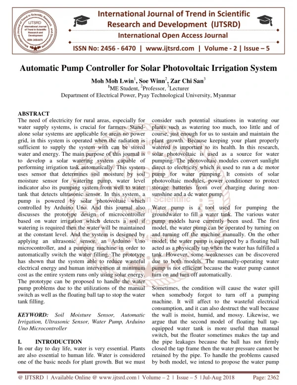
The Earth receives 174 peta watts PW of incoming solar radiation at the upper atmosphere. Approximately 30 is reflected back to space while the rest is absorbed. Solar energy is an alternative for fossil fuels as it is non polluting, clean, reliable and renewable source of energy. It does not pollute the air by releasing harmful gases like carbon dioxide, nitrogen oxide or sulphur oxide. So, the risk of damage to the environment is reduced. Thus the use of solar devices was more suggested and the traffic signal and street lights in villages was installed using solar panel but the solar PV modules are generally employed in the dusty environments and the dust gets accumulated on the front surface of the module and blocks the incident light form the sun and it reduces the power generation capacity of the module, the power output reduces if the module is not cleaned for a regularly. In order to regularly clean the dust, this research presents a control application of a sun tracker that is able to follow the sun with high accuracy and clean the dust on the panel without the necessity of either a precise procedure of installation or recalibration. The designed tracking system consists of sensors, microcontroller, drivers for dc motors and gear bearing arrangements with supports and mountings. DC motor is used to move the system panel so that sun's beam is able to remain aligned with the solar panel and also clean the dust on the panel which improves the efficiency of the solar panel. Simulation and experimental results are obtained to a low cost single axis solar tracker and are exposed. Energy saving factors are taken into account, which implies that, among other factors, the sun is not constantly tracked with the same accuracy, to prevent energy over consumption by the motors. Kavya S Gogi | Maheshan CM | H Prasanna Kumar "Automatic Solar Tracker with Dust Wiper Using PID Controller" Published in International Journal of Trend in Scientific Research and Development (ijtsrd), ISSN: 2456-6470, Volume-2 | Issue-1 , December 2017, URL: https://www.ijtsrd.com/papers/ijtsrd7197.pdf Paper URL: http://www.ijtsrd.com/engineering/automotive-engineering/7197/automatic-solar-tracker-with-dust-wiper-using-pid-controller/kavya-s-gogi<br>

E N D
International Research Research and Development (IJTSRD) International Open Access Journal International Open Access Journal International Journal of Trend in Scientific Scientific (IJTSRD) ISSN No: 2456 - 6470 | www.ijtsrd.com | Volume ISSN No: 2456 | www.ijtsrd.com | Volume - 2 | Issue – 1 Automatic Solar Tracker with Dust Wiper Using PID Controller Automatic Solar Tracker with Dust Wiper Using PID Controller Automatic Solar Tracker with Dust Wiper Using PID Controller Kavya S Gogi Kavya S Gogi 1, Maheshan CM 2, H Prasanna Kumar 2 P.G Scholar, Department of Electrical Engineering, UVCE, Bangalore, India, Assistant Professor, Department of Electrical engineering, UVCE, Bangalore, India 1P.G Scholar, Department of Electrical Engineering, UVCE, Bangalore, India, 2Assistant Professor, Department of Electrical engineering, UVCE, Bangalore, India Assistant Professor, Department of Electrical engineering, UVCE, Bangalore, India P.G Scholar, Department of Electrical Engineering, UVCE, Bangalore, India, ABSTRACT The Earth receives 174 peta watts (PW) of incoming solar radiation at the upper atmosphere. Approximately 30% is reflected back to space while the rest is absorbed. Solar energy is an alternative for fossil fuels as it is non-polluting, clean, reliable and renewable source of energy. It does not pollute the air by releasing harmful gases like carbon dioxide, nitrogen oxide or sulphur oxide. So, the risk of damage to the environment is reduced. Thus the use of solar devices was more suggested and the traffic signal and street lights in villages was installed using solar panel but the solar PV modules are generally employed in the dusty environments and the dust gets accumulated on the front surface of the module and blocks the incident light form the sun and it reduces the power genera capacity of the module, the power output reduces if the module is not cleaned for a regularly. In order to regularly clean the dust, this research presents a control application of a sun tracker that is able to follow the sun with high accuracy and clean the dust on the panel without the necessity of either a precise procedure of installation or recalibration. The designed tracking system consists of sensors, microcontroller, drivers for dc motors and gear- bearing arrangements with supports and mountings. DC motor is used to move the system panel so that sun’s beam is able to remain aligned with the solar panel and also clean the dust on the panel which improves the efficiency of the solar panel. Simulation and experimental results are obtained to a low cost single axis solar tracker and are exposed. Energy saving factors are taken into account, which implies that, among other factors, the sun is not constantly tracked with the same accuracy, to prevent energy over consumption by the motors. watts (PW) of incoming Keywords: Solar Panel, Dust wiper, PID controller, Acclerometer, DC motor. I. INTRODUCTION olar Panel, Dust wiper, PID controller, solar radiation at the upper atmosphere. Approximately 30% is reflected back to space while the rest is absorbed. Solar energy is an alternative for fossil fuels polluting, clean, reliable and renewable . It does not pollute the air by releasing harmful gases like carbon dioxide, nitrogen oxide or sulphur oxide. So, the risk of damage to the environment is reduced. Thus the use of solar devices was more suggested and the traffic signal and street n villages was installed using solar panel but the solar PV modules are generally employed in the dusty environments and the dust gets accumulated on the front surface of the module and blocks the incident light form the sun and it reduces the power generation capacity of the module, the power output reduces if the module is not cleaned for a regularly. In order to regularly clean the dust, this research presents a control application of a sun tracker that is able to follow the Currently, many alternative energy sources appear to be technically useful. One of them is solar energy. The panels are the fundamental solar component. Conventional solar panels, fixed with a certain angle, limit their area of exposure from the sun during the course of the day. Therefore, the average solar energy is not always maximized. Sun systems are essential for many applications such as thermal energy storage systems and solar energy based power generation systems in order to improve system performance. The system always keeps the plane of the panel normal to the direction of the sun. By doing so, maximum irradiation and thermal energy would be taken from the sun. The elevation angle of the sun remains almost invariant in a month and varies little in a year. Therefore, a single axis position control scheme may be sufficient for the collection of solar energy in some applications. In flat panel applications, trackers are used to minimize the angle of incidence between the incoming sunlight and a photovoltaic panel. Thus increases the amount of energy produced from a fixed amount of installed power generating capacity. photovoltaic (CPV) and concentrated solar thermal (CSP) applications, trackers are used to enable the optical components in the CPV and CSP systems. The optics in concentrated solar applications accepts the direct component of sunlight light and th be oriented appropriately to collect energy. Tracking be oriented appropriately to collect energy. Tracking Currently, many alternative energy sources appear to be technically useful. One of them is solar energy. The panels are the fundamental solar-energy conversion entional solar panels, fixed with a certain angle, limit their area of exposure from the sun during the course of the day. Therefore, the average solar energy is not always maximized. Sun-tracking systems are essential for many applications such as energy storage systems and solar energy based power generation systems in order to improve system performance. The system always keeps the plane of the panel normal to the direction of the sun. By doing so, maximum irradiation and thermal energy would be taken from the sun. The elevation angle of the sun remains almost invariant in a month and varies little in a year. Therefore, a single axis position control scheme may be sufficient for the collection of solar energy in some applications. In flat panel photovoltaic (PV) applications, trackers are used to minimize the angle of incidence between the incoming sunlight and a photovoltaic panel. Thus increases the amount of energy produced from a fixed amount of installed power generating capacity. photovoltaic (CPV) and concentrated solar thermal (CSP) applications, trackers are used to enable the optical components in the CPV and CSP systems. The optics in concentrated solar applications accepts the direct component of sunlight light and therefore must ean the dust on the panel without the necessity of either a precise procedure of installation or recalibration. The designed tracking system consists of sensors, microcontroller, drivers for bearing arrangements with ngs. DC motor is used to move the system panel so that sun’s beam is able to remain aligned with the solar panel and also clean the dust on the panel which improves the efficiency of the solar panel. Simulation and experimental results are obtained w cost single axis solar tracker and are exposed. Energy saving factors are taken into account, which implies that, among other factors, the sun is not constantly tracked with the same accuracy, to prevent In In concen concentrated @ IJTSRD | Available Online @ www.ijtsrd.com @ IJTSRD | Available Online @ www.ijtsrd.com | Volume – 2 | Issue – 1 | Nov-Dec 2017 Dec 2017 Page: 1422
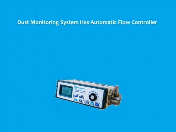
International Journal of Trend in Scientific Research and Development (IJTSRD) ISSN: 2456-6470 systems are found in all concentrator applications because such systems do not produce energy unless pointed at the sun. Global power consumption currently stands at approximately 15 TW the vast majority of which is generated by the combustion of fossil fuels. The associated release of carbon di oxide from these anthropogenic sources has dramatically altered the composition of the atmosphere and may detrimentally impact global temperature, sea levels, and weather patterns. The terawatt challenge is the effort to supply up to 30 TW of carbon-free power by the mid-21st century. which is the case in tropical countries like India. The dust gets accumulated on the front surface of the module and blocks the incident light from the sun. It reduces the power generation capacity of the module. The power output reduces as much as by 50% if the module is not cleaned for a month. In order to regularly clean the dust, a automatic cleaning system has been designed, which senses the dust on the solar panel and also cleans the module automatically. This automated system is implemented using 8051 microcontroller which controls the DC gear motor. This mechanism consists of a sensor (LDR). While for cleaning the PV modules, a mechanism consists of a sliding brushes has been developed. In terms of daily energy generation, the presented automatic-cleaning scheme provides about 30% more energy output when compared to the dust accumulated PV module. PROBLEM STATEMENT A solar tracker is used in various systems for the improvement of harnessing of solar radiation. The problem that is posed is the implementation of a system which is capable of enhancing production of power by 30-40%. The dust collected on the solar panel reduces the efficiency of the panel decreasing or lowering the panel output. 2. A Performance Analysis of Brushless DC Motor by using PID Controller-Kautik R. Patil-PG Student, Department of Electrical Engineering, Matsyodari Shikshan Sanstha’s, College of Engineering and Technology Nagewadi, Jalna. Increase in need of industry for high productivity is placing new demands on mechanisms connected with electrical motors. This leads different problems in operation due to fast dynamics and instability. The stability of the system is essential to work at desired set targets. The non- linear effects caused by a motor frequently reduce stability, which reduces the controller’s ability to maintain speed or position at set points. Hence number of the industrial process applications requires speed & position control of DC motor. A brushless DC motor described as magnet being the rotor and its stationary windings forming the stator. This design provides many advantages over the brush DC motor. Brushless DC (BLDC) motor drives are becoming widely used in various consumer and industrial systems, such as servo motor drives, home appliances, computer peripherals, and automotive applications in recent years because of their high efficiency, silent operation, compact form, reliability, and low maintenance. OBJECTIVE The main objective is to obtain maximum efficiency from single axis solar tracking system and to clean the solar panel at regular intervals of time to improve the efficiency of the panel. To achieve this objective 1.Single axis solar tracker to be built using the Sensors. 2.PID algorithm has to be implemented for solar panel tilt error minimization. 3.To achieve efficiency of the solar panel voltage using Windshield wiper. 4.Aim to implement prototype system. II. LITERATURE SURVEY Literature review has information on the papers that has been referred to have a brief idea on the prototype model implementation, four papers mentioned below has been reviewed to analyze the single axis tracking, real time tilt and voltage monitoring and tilt error minimization using PID. 3. Tracking of Sun for Solar Panels and Real Time Monitoring Using LabVIEW-Bipin Krishna, Manipal Institute of Technology, Department of Instrumentation & Control. Sun is a very abundant source of power. Even so, only a fraction of the entire energy is harnessed and that too not efficiently. The main cause of this is the high cost of installation of solar cells. Also solar cells are mostly kept fixed, so they do not obtain the optimum amount of sunlight throughout the day. The development of a simple process to track the sun 1. Microcontroller based Automatic cleaning of Solar Panel -S. B. Halbhavi-Department of Electrical & Electronics Engineering, Technology, Belgaum Karnataka, India. The solar PV modules are generally employed in dusty environments Gogte Institute of @ IJTSRD | Available Online @ www.ijtsrd.com | Volume – 2 | Issue – 1 | Nov-Dec 2017 Page: 1423
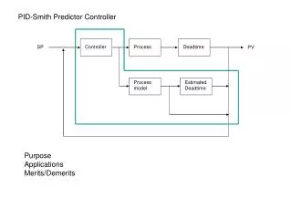
International Journal of Trend in Scientific Research and Development (IJTSRD) ISSN: 2456-6470 and attain maximum efficiency using Microcontroller and LabVIEW for real time monitoring. which means that the solar panel is facing the sun and the light intensities falling on the four LDRs are equal or slightly different. 4. Self-Cleaning and Tracking Solar Photovoltaic Panel for Improving Efficiency- Bandam Abhilash, Department of Electrical Engineering Indian Institute of Technology, Bombay Powai, Electricity is one of the basic necessities of mankind. As the demand of electricity is increasing, there is need to exploit renewable sources of energy. power shortage in India, the use of solar energy could be beneficial to great extent. The number and size of the Photovoltaic (PV) systems are growing and consequently the amount of the investments and the related opportunities and risks are increasing. To make solar energy more fruitful, the efficiency of solar array systems must be maximized. For the efficiency evaluation of PV panels, that has been discussed with particular attention to the presence of dust and maximum intensity of light on the panel surface. Mainly, the effects of the dust and intensity of light on the efficiencies of the PV panels have been highlighted. This paper gives the brief description of the design and construction of microcontroller based cleaning and tracking system. In general, the panel should be rotated towards East direction in order to make it ready for operation on the next day. Mumbai-400076- Block Diagram of solar tracking and Panel Cleaning The figure 2 shows the panel placed with 4 LDRs which conducts and passes current according to intensity of light. These value of voltage is read by arduino controller and then computes the difference in voltage of intensity of LDRs to achieve the maximum direction facing solar panel towards sun by controlling the axis by the help of DC motor which is controlled using PWM and PID controller as shown below. The accelerometer is placed on top of the panel to monitor the axis direction in terms of degree. III. METHODOLOGY The main concept of the solar-tracking system is to sense the sun light by using four light dependent resistors (LDRs). Each LDR is fixed inside the hallow cylindrical tubes. For controlling the angle of tilt positioned towards the direction of maximum sunlight, the LDR assembly is fixed onto the flat-solar panel, shown in Figure 1. The differential signals of each pair of LDRs representing the angular error of the solar panel are employed to re-position the panel in such a way that the angular errors are minimized. If the difference between LDR1 + LDR2 and LDR3 + LDR4, gives error signal that is minimized using PID controller. Figure 2, block diagram Figure also shows the block diagram of close loop PID system of DC motor. The input variable of the PID controller is the velocity error ωe calculated as difference between the LDRs voltage values. The actual velocity of motor, in revolutions per minute (RPM), is calculated based on frequency of encoder waveform multiplied by 60. RPM = ?∗?? ?? Where f is the frequency of encoder waveform and Ns is the number of pulses per revolution (equal with the number of transparent sections from encoder disk). A frequency variation of 1 Hz corresponds to RPM Figure 1, Front surface of Solar panel with LDR’s at panel ends. If the error signals are smaller than or equal to the value of tolerance, arduino controller generates no signal; @ IJTSRD | Available Online @ www.ijtsrd.com | Volume – 2 | Issue – 1 | Nov-Dec 2017 Page: 1424
International Journal of Trend in Scientific Research and Development (IJTSRD) ISSN: 2456 International Journal of Trend in Scientific Research and Development (IJTSRD) ISSN: 2456 International Journal of Trend in Scientific Research and Development (IJTSRD) ISSN: 2456-6470 variation of 60, due to the low resolution (PPR=1 reduce this dependence a median filter is used. reduce this dependence a median filter is used. variation of 60, due to the low resolution (PPR=1). To option. Most of these cleaning systems work like windshield wipers, brushing dust away from the solar nd mechanical arm. Consider cleaning panels for large commercial or public utility sites, especially those in remote, dry, or option. Most of these cleaning systems work like windshield wipers, brushing dust away from the solar panels with a spray hose and mechanical arm. Consider self-cleaning panels for large commercial or public utility sites, especially those in remote, dry, or hazardous locations. The PID controller adjusts the output voltage level of the H-bridge circuit by increasing or decreasing the duty cycle of the PWM signal. The PID controller adjusts the output voltage level of bridge circuit by increasing or decreasing the Wipers may be powered by a variety of means, although most in use today are powered by an electric r through a series of mechanical components, bar linkages in series or parallel and vehicles with air operated brakes sometimes use pneumatic wipers which are powered by tapping a small amount of pressurized air from the brake system mall air operated motor mounted on or just above the windscreen. These wipers are activated by opening a valve which allows pressurized air to enter the motor .The Early wipers were often driven by a vacuum motor powered by manifold vacuum. This had the drawback that manifold vacuum varies depending on throttle Wipers may be powered by a variety of means, although most in use today are powered by an electric motor through a series of mechanical components, typically two 4-bar linkages in series or parallel and vehicles with air operated brakes sometimes use pneumatic wipers which are powered by tapping a small amount of pressurized air from the brake system to a small air operated motor mounted on or just above the windscreen. These wipers are activated by opening a valve which allows pressurized air to enter the motor .The Early wipers were often driven by a vacuum motor powered by manifold vacuum. This had the dr that manifold vacuum varies depending on throttle position, and is almost non-existent under wide throttle, when the wipers would slow down or even stop. This problem was overcome somewhat by using a combined fuel or vacuum booster pump. combined fuel or vacuum booster pump. Figure 3, dc motor control block diagram Figure 3, dc motor control block diagram The H-bridge L298n is used as motor driver to control the motor from Lab VIEW via Arduino board and Arduino provides control signals to the DC motor and allows to drive motors in both directions, clockwise (CW) or counter-clockwise (CCW), by reversing the polarity of the motor supply voltage. The main components are four switching elements S1, S2, S3 and S4 (transistors), actuated diagonally. The block diagram of the used H-bridge circuit is shown. used as motor driver to control the motor from Lab VIEW via Arduino board and Arduino provides control signals to the DC motor and allows to drive motors in both directions, clockwise clockwise (CCW), by reversing the supply voltage. The main components are four switching elements S1, S2, S3 and S4 (transistors), actuated diagonally. The block diagram existent under wide-open throttle, when the wipers would slow down or even stop. This problem was overcome somewhat by using a Windshield wiper is a mechanical sweeper that wipes water off a windshield. Arm Articulation is a part that attaches the wipes blade to the arm. Blade is apart that supports the wiper and is attached to the wiper arm. Wiper rubber rubber used to wipe the window. grooved axle that rotates the wiper arm. grooved axle that rotates the wiper arm. is a mechanical sweeper that wipes Arm is a movable part. is a part that attaches the wipes blade to the is apart that supports the wiper and is Wiper rubber is a piece of rubber used to wipe the window. Fluted shaft is a Figure 4, H-bridge circuit diagram bridge circuit diagram The operation of an H-bridge circuit is described as follows. The motor has two leads. To turn the motor in CW direction, a positive voltage will be applied to the left lead, and the right lead should be connected to ground. In this case S1 and S4 are switched on, and S2 and S3 are switched off. Inverse, if we want to rotate the motor in CCW direction, S1 and S4 are switched off, and S2 and S3 are switched on. The voltage polarity is reversed and this fact causes the motor to rotate in the opposite direction. bridge circuit is described as follows. The motor has two leads. To turn the motor in CW direction, a positive voltage will be applied to the left lead, and the right lead should be connected to Figure 5 ,Windshield wiper. Figure 5 ,Windshield wiper. ched on, and S2 and S3 are switched off. Inverse, if we want to rotate the motor in CCW direction, S1 and S4 are switched off, and S2 and S3 are switched on. The voltage polarity is reversed and this fact causes the motor to Solar panel cleaning For solar panels in hard to reach areas, automatic cleaning systems and cleaning robots are a popular cleaning systems and cleaning robots are a popular For solar panels in hard to reach areas, automatic @ IJTSRD | Available Online @ www.ijtsrd.com @ IJTSRD | Available Online @ www.ijtsrd.com | Volume – 2 | Issue – 1 | Nov-Dec 2017 Dec 2017 Page: 1425
International Journal of Trend in Scientific Research and Development (IJTSRD) ISSN: 2456 International Journal of Trend in Scientific Research and Development (IJTSRD) ISSN: 2456 International Journal of Trend in Scientific Research and Development (IJTSRD) ISSN: 2456-6470 Figure 5.6 Hardware Module Setup Figure 5.6 Hardware Module Setup The above figure shows the hardware working module setup of final develeped prototype module setup of final develeped prototype module The above figure shows the hardware working module Figure 8, Front panel showing control parameters Figure 8, Front panel showing control parameters Front panel for Solar Tracking In the above figure 8, the temperature and angle calibration scales are used to remove offset. Also, the PID values are also shown. The wiper initialization and controlling parameters are also controlling parameters are also shown. In the above figure 8, the temperature and angle calibration scales are used to remove offset. Also, the PID values are also shown. The wiper initialization and IV - RESULTS AND DISCUSSION RESULTS AND DISCUSSION Solar panel voltage and power output results Solar panel voltage and power output results time Voltag e (V) 6 AM 3.16 0.0632 7 AM 6.32 0.1264 8 AM 10.34 0.2049 9 AM 15.32 0.3065 10 AM 17.60 0.3520 11 AM 19.87 0.3974 12 PM 20.12 0.4024 1 PM 19.23 0.384 2 PM 18.9 0.377 3 PM 19.49 0.387 4 PM 17.88 0.3577 5 PM 14.14 0.2828 6 PM 3.87 0.0774 7 PM 1.4 0.028 The tabular column gives the information of how the voltage, current and power varies for a tilt panel according to time. current (A) Resistance (ohm) 50 50 50 50 50 50 50 50 50 50 50 50 50 50 power 0.2 0.8 2.1 4.7 6.2 7.9 8.1 7.4 7.14 7.6 6.4 4 0.3 0.039 Figure 7, Front panel display of solar tracker, LDRs Variation and panel tilt angle Variation and panel tilt angle Figure 7, Front panel display of solar tracker, LDRs The above figure 7, shows temperature of the solar panel as well as its tilt angle based on the actual position of the sun in real time and it varies from to +140 degrees. The LDR sensors which are placed on either side of the panel are shown in figure. either side of the panel are shown in figure. The above figure 7, shows temperature of the solar panel as well as its tilt angle based on the actual it varies from -140 to +140 degrees. The LDR sensors which are placed on The sensitivity voltage output of all the four LDR’s will be displayed on the front panel. The differential error between the sum of LDR1+LDR2 and the sum of LDR3+LDR4 is shown in error meter. The sensitivity voltage output of all the four LDR’s will be displayed on the front panel. The differential error R1+LDR2 and the sum of When the wiper starts wiping the solar panel light is indicated on the front panel at that time the tracking is stopped for few seconds or minutes as per calibration of the wiper delay parameter . r starts wiping the solar panel, a green light is indicated on the front panel at that time the tracking is stopped for few seconds or minutes as per The tabular column gives the information of how the voltage, current and power varies for a tilt panel @ IJTSRD | Available Online @ www.ijtsrd.com @ IJTSRD | Available Online @ www.ijtsrd.com | Volume – 2 | Issue – 1 | Nov-Dec 2017 Dec 2017 Page: 1426
International Journal of Trend in Scientific Research and Development (IJTSRD) ISSN: 2456-6470 The dust falling on the solar panel was wiped for regular intervals of time , thus increasing the efficiency and life of the solar panel thus overcoming two major disadvantage of solar panel real time use. VI - FUTURE WORK The dual axis is recommended upon large systems where a high power generation is required, that is because the annual axis increasing power during the year, so when considering a single solar panel of (36W) the saved power will be a very small fraction of that. Dust sensor with high sensitivity can be used in order to automatically clean the solar panel rather regular time intervals using fuzzy logic. Real time monitoring of the entire plant can be implemented using SCADA or HMI Figure 9, Graph representing the Time versus voltage/power /current. REFERENCES I-V Characteristic curve of the analysis 1)Microcontroller based Automatic cleaning of Solar Panel -S. B. Halbhavi-Department of Electrical & Electronics Engineering, Technology, Belgaum Karnataka, India. 2015 A current-voltage (I-V) curve shows the possible combinations of current and voltage output of a photovoltaic device. A PV device, such as a solar module, produces its maximum current when there is no resistance in the circuit that is when there is a short circuit between its positive and negative terminals. Gogte Institute of 2)A Performance Analysis of Brushless DC Motor by using PID Controller-Kautik R. Patil-PG Student, Department of Electrical Engineering, Matsyodari Shikshan Sanstha’s, College of Engineering and Technology Nagewadi, Jalna. 2010 3)Tracking of Sun for Solar Panels and Real Time Monitoring Using LabVIEW-Bipin Manipal Institute of Technology, Department of Instrumentation & Control. 2014 Krishna, 4)4. Self-Cleaning and Tracking Solar Photovoltaic Panel for Improving Efficiency- Bandam Abhilash, Department of Electrical Engineering Indian Institute of Technology, Bombay Powai, Mumbai- 400076. 2014 Figure 10, I-V characteristics of the experimental analysis. 5)Naveenkumar, R. and D.P. Krishna, Low Cost Data Acquisition and Control using Arduino Prototyping Platform and LabVIEW. International Journal of Science and Research, 2013. 2(2): p. 366-369. V - CONCLUSION A single axis solar tracker that can produce maximum voltage and turn in particular direction depending upon the light intensity falling on the light dependent resistors was built successfully and the analysis of the prototype system was done and PID Algorithm was applied to minimize the solar panel tilt error. 6)Zouari, F., K.B. Saad, and M. Benrejeb, Adaptive Internal Model Control of a DC Motor Drive System Using Dynamic Neural Network. Journal of Software Engineering and Applications, 2012. 5(03): p. 168. LDR characteristics were analyzed and single axis solar tracker is simulated and tested successfully. @ IJTSRD | Available Online @ www.ijtsrd.com | Volume – 2 | Issue – 1 | Nov-Dec 2017 Page: 1427