Download
1 / 3
50 likes | 129 Views
On load tap changing transformers play important roles in any modern power system since they allow voltages to be maintained at desired levels despite load changes. Traditionally, on load tap changer is a complex mechanical device, which has some deficiencies. On load tap changer of a transformer is presented, which can eliminate excessive conduction losses and suppress the arcing in the diverter switch, which is inherent in traditional on load transformer tap changers. The OLTC provides uninterrupted voltage is regulation of transformers under load. The transformer is equipped with a tapped winding whose tappings are connected with the tap selector of the OLTC. Most of the current commercially available automatic voltage regulators, just measure the low voltage side of the power transformer in order to control OLTC position. In this to improve tap changer control in order to perform properly also during a stressed situation in the 230 33 kV regulating power transformer for the substation. Zin Wah Aung | Aung Thike "Analysis of on Load Tap Changing Transformer for Substation" Published in International Journal of Trend in Scientific Research and Development (ijtsrd), ISSN: 2456-6470, Volume-3 | Issue-5 , August 2019, URL: https://www.ijtsrd.com/papers/ijtsrd26556.pdf Paper URL: https://www.ijtsrd.com/engineering/electrical-engineering/26556/analysis-of-on-load-tap-changing-transformer-for-substation/zin-wah-aung<br>

E N D
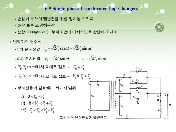
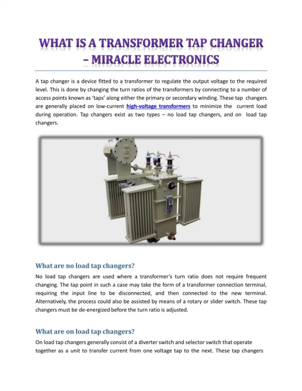
International Journal of Trend in Scientific Research and Development (IJTSRD) Volume 3 Issue 5, August 2019 Available Online: www.ijtsrd.com e-ISSN: 2456 – 6470 Analysis of on Load Tap Changing Transformer for Substation Zin Wah Aung, Aung Thike Lecturer, Electrical Power Department, Technological University, Mandalay, Myanmar How to cite this paper: Zin Wah Aung | Aung Thike "Analysis of on Load Tap Changing Transformer for Substation" Published in International Journal of Trend in Scientific Research and Development (ijtsrd), ISSN: 2456- 6470, Volume-3 | Issue-5, August 2019, https://doi.org/10.31142/ijtsrd26556 Copyright © 2019 by author(s) and International Journal of Trend in Scientific Research and Development Journal. This is an Open Access article distributed under the terms of the Creative Commons Attribution License (CC (http://creativecommons.org/licenses/by /4.0) These systems usually posses 33 taps (one at the centre “Rated tap and sixteen to increase and decrease the turn ratio) and allow for ±8% variation (each step proving 1.65% variation) from the nominal transformer rating which, in turn, along for stepped voltage regulation of the output. Tap changers are often placed on the high voltage (low current) transformer winding for easy access and to minimize the current load during operation. ON-Load Tap Change: Most of the Generating Station, Substation system having Power Transformer with On-Load Tap Changer (OLTC). Not only in Generating Station Transformer but also in Distribution Class Transformer too. In this substation, there are three windings; such as primary winding, secondary winding and tertiary winding. Among them, we will neglect the tertiary winding which is used for residential houses. 2. LITERATURE REVIEW Transformers are essential for the transmission, distribution, and utilization of alternating current electrical energy. In more technical terms, a power transformer is composed of two or more windings which, by electromagnetic induction, transform a system of alternating voltage and current into another system of voltage and current for the purpose of transmitting electrical power. Mainly the regulation of voltage is achieved by altering the ratio of transformation by tapping the winding, so as to alter the number of turns. The process of altering the ratio of transformation by tapping the windings is termed as tap changing. Tapping may be changed mainly in two different ways; When the transformer is disconnected from the supply, called as, offload tap changing. When the transformer is operating on load (without de- ABSTRACT On-load tap changing transformers play important roles in any modern power system since they allow voltages to be maintained at desired levels despite load changes. Traditionally, on-load tap changer is a complex mechanical device, which has some deficiencies. On-load tap changer of a transformer is presented, which can eliminate excessive conduction losses and suppress the arcing in the diverter switch, which is inherent in traditional on-load transformer tap changers. The OLTC provides uninterrupted voltage is regulation of transformers under load. The transformer is equipped with a tapped winding whose tapping's are connected with the tap selector of the OLTC. Most of the current commercially available automatic voltage regulators, just measure the low voltage side of the power transformer in order to control OLTC position. In this to improve tap-changer control in order to perform properly also during a stressed situation in the 230/33 kV regulating power transformer for the substation. KEYWORDS: load changes, tap changer, diverter switch, voltage regulation, power transformer for substation 1. INTRODUCTION A tap changer is a mechanism in transformers which allows for variable turn ratios to be selected in discrete steps. Transformers with this mechanism obtain this variable turn ratio by connecting to a number of access points known as taps along either the primary or secondary winding. IJTSRD26556 pp.1144-1146, BY 4.0) energized), known as on-load tap changing. During offload tap changing, the transformer is completely de-energized, in order to avoid arcing at the point of breath. The method of offload tap changing is not suitable for large power supply systems. This system call for power transformer with a voltage regulating winding, the tapping of which are changed over under loaded condition by on-load tap changer. The schemes employed for on-load tap changer involved the use of more complicated and expensive tap changing equipment. As such, power transformers with on-load tap changing arrangement are larger in size, have a greater height and consequently more costly compared to the transformer of same output and voltage, but provided with off-load tap changer. Due to the higher cost of the on-load tap changer, normally small and medium rating of transformers is provided with off-load tap changer. Larger rating transformers are provided with on-load tap changer because frequent discontinuity of power cannot be tolerated by the power system network. 3. STUDYING DESIGN TRANSFORMER For design and calculation of on-load tap changing transformer are calculated by using the following equations. e.m.f per turns, Et=4.44fBmAi (1) THEORY OF OLTC ??? ????? (2) Et=K? @ IJTSRD | Unique Paper ID – IJTSRD26556 | Volume – 3 | Issue – 5 | July - August 2019 Page 1144
International Journal of Trend in Scientific Research and Development (IJTSRD) @ www.ijtsrd.com eISSN: 2456-6470 Table1. Values of Factor, K Type of Transformer Three phase core type (power) Three phase core type (distribution) 0.45 to 0.5 Three phase shell type Single phase core type Single phase shell type Distribution transformers Power transformers Large transformers with forced -3 to 4.5 A/mm2 Area of the window Aw=L(D-d) Width of the window bw= (D-d)for various stepped core The overall length of the yoke, W= 2D+0.9d (for three-phase, three stepped) Area of yoke Ay 1.1to 1.15Ai Width of the yoke by= 0.9 d(for three stepped core) 4. SPECIFICATIONS TO DESIGN A design based on the following typical specifications. Rating -100MVA No. of phase -Three phase Frequency -50Hz Voltage ratio -230/33kV at no-load Percentage tapping -±8×1.65% No. of tapping -17 positions Connection -HV star, LV star Cooling -Oil natural air natural (ONAN) Type -Core type, cold-rolled silicon steel sheet Location -Outdoor 5. RESULT DATA OF ON LOAD TAP CHANGING TRANSFORMER Total iron losses =0.2 % (within limit) The iron losses in small transformer may be of the order of 0.5 to 1 % of rated output. In large and small transformers, iron losses should be within 0.2 to 0.5 % of rated output. Percentage no-load current =0.53% (within limit) The no-load current of a small transformer may be of the order of 3 to 5 percent of the rated current, whereas in medium transformers, it varies from 1 to 3 percent. In the case of large transformers, no-load current may be from0.5 to 2 percent of the rated current within the proper range. Tapping result Rated tap and sixteen to increase and decrease the turn ratio and allow for Rated tap and sixteen to increase and decrease the turn ratio and allow for ±8% variation (each step proving 1.65% variation) from the nominal transformer rating which, in turn, along for stepped voltage regulation of the output. Efficiency At full load (0.8 p.f) = 99% (within limit) At full load (unity) = 99% (within limit) At half load (0.8 p.f) = 98.8% (within limit) At ¾ load (0.8 p.f) = 99.2% (within limit) The efficiency of the small transformer may be of the order of 98%, whereas for medium and large transformer, its values are from 98.0 to 99.2% -2.00 to 2.5 A/mm2 - 2.3 to 3.5 A/mm2 Factor, K 0.6 to 0.7 1.2 to 1.3 0.75 to 0.8 1 to 1.1 Ai=ksAgi (3) ks = stacking factor, usual value is 0.85 – 0.9 Output equation of three phase transformer Q=3.33 f Bm δ ki Aw Ai× 10-3 (kVA) (4) η = Number of turns per phase, T1 = T2× 3.1 Specific Magnetic loading, Bm Normally two types of sheet steel are used for the core and yoke of transformers A.hot rolled silicon steel. B.cold rolled grain oriented silicon steel. Using hot rolled silicon steel. Power transformers -1.2 to 1.4 Tesla Distribution transformers - 1.1 to 1.3 Tesla Using hot rolled silicon steel. Power transformers -1.5 to 1.7 Tesla Distribution transformers -1.4 to 1.5 Tesla Window space factor Kw = Table 2.Window Space Factor kw kVA 3.3kV 11kV 33kV 110kV 100 0.27 0.2 1000 0.38 0.28 2000 0.4 0.3 5000 0.42 0.34 10000 0.45 0.37 Effects of kVA rating on the above value of window space are the following facts. 1.The above values are quite satisfactory for transformers between 50 to 250 kVA. 2.The above values may be reduced by 5 to 20% for transformers rated between 5kVA to 50kVA. 3.The above value may be increased by 5 to 20% for transformer above 250 kVA. The net cross-sectional area of the core 3.2 Current Density, δ The current density for H.V winding should be taken comparatively higher, compared to the current density for L.V winding, because cooling conditions are better in the L.V winding. ?????? ????? ?????? ?????????? ?????? × 100 % (5) ?? ?? (6) ?? ?????? 0.14 0.2 0.24 0.26 0.29 - 0.15 0.16 0.18 0.2 @ IJTSRD | Unique Paper ID – IJTSRD26556 | Volume – 3 | Issue – 5 | July - August 2019 Page 1145
International Journal of Trend in Scientific Research and Development (IJTSRD) @ www.ijtsrd.com eISSN: 2456-6470 Table3. OLTC Positions for 230kV Side of 100MVA Power Transformer Tap Position turns(turns) 1 1.65% 2 3.30% 3 4.95% 4 6.60% 5 8.25% 6 9.90% 7 11.55% 8 13.20% 9 0% 10 -1.65% 11 -3.30% 12 -4.95% 13 -6.60% 14 -8.25% 15 -9.90% 16 -11.55% 17 -13.2% 7. The author deeply wants to express special appreciation and heart-left thanks to Dr. Yadana Aung, Professor and Head the Department of Electrical Power Engineering, Technological University (Mandalay) for her willingness to share her ideas and helpful suggestions on this paper writing. 8. REFERENCES [1][13Die] Dieter Dohnal, Dr.: On-Load Tap Changers for Power Transformers, Maschinenfabrik Reinhausen GmbH in Regensburg, Germany, 2013, www.reinhausen.com ACKNOWLEDGMENTS Number of H.V Side Voltage(Volts) 260360 256565 252770 248975 245180 241385 237590 233765 230000 226205 222410 218615 214820 211025 207230 203435 199640 Tap 2408 2363 2320 2280 2238 2200 2162 2126 2090 2057 2024 1992 1961 1931 1902 1874 1847 MR knowledge base, [2][12Han] Hans Linder: On-Load Tap Changer, Type UC, Technical Guide, Power and productivity, ABB AB Components, SE-771 (80) LUDVIKA, Sweden, (2012) [3][1 1Ele] Transformers, Reference and application, Turkey, 2011, www.abb.com/tr ABB Elektrik Sanayi A.S.: Power [4][11 Smi] Dr. J. J. Smith: On-Load Tap Changer Diagnosis on High-Voltage Power Transformer using Dynamic Resistance Measurements, Technische Universiteit Delft, Switzerland, (2011) 6. This thesis was intended for design calculation of OLTC power transformer. OLTC theory, operation and example application with Myaukpyin Substation is also described in this thesis. Presently available technical solutions enable the production of OLTCs that are reliable and meet the same life expectancy as transformers. At the percent time and for the foreseeable future, the proper implementation of the vacuum switching technology in OLTCs provides the best formula of quality, reliability, and economy achievable a maintenance-free design. CONCLUSIONS [5][04Die] Power Transformers, A Technical Digest, MR Publicatin, (2004) Dieter Dohnal: On-Load Tap Changers for [6][01Ano] ABB Power Technology Products, Switzerland 2001, www.abb.com Limited, McGraw- Hill Publishing Company Limited, Anonymous: Oil-type Power Transformers, [7][96Mit] Electrical Machine, 5th Edition, Dtandard Publishers Distrbutors, (1996) Mittle, V.N. And Arvind Mittal.: Design of @ IJTSRD | Unique Paper ID – IJTSRD26556 | Volume – 3 | Issue – 5 | July - August 2019 Page 1146