Download
1 / 6
60 likes | 76 Views
Diagnostic methods for two major cables, PVC and XLPE cables, are presented. As a new diagnostic method for the PVC cable insulation, an analysis of the insulation oil sampled from the splices or the end sealing box is proposed. As for diagnostic methods for the XLPE cable insulation, several methods are described to detect water tree deterioration, which is the only major problem with XLPE cables. These methods are classified into off line and live line tests. Especially, newly proposed diagnostic methods are discussed, which can be applied to live line XLPE cables. These are a measuring method of dc current component in ac charging current of cables containing water trees, a method to measure insulation resistance, and a method of detecting electrical tree deterioration in XLPE cable. Vikas | J. S. Arya "A Review on Distribution Cables and Their Diagnostic Methods" Published in International Journal of Trend in Scientific Research and Development (ijtsrd), ISSN: 2456-6470, Volume-2 | Issue-6 , October 2018, URL: https://www.ijtsrd.com/papers/ijtsrd18829.pdf Paper URL: http://www.ijtsrd.com/engineering/electrical-engineering/18829/a-review-on-distribution-cables-and-their-diagnostic-methods/vikas<br>

E N D
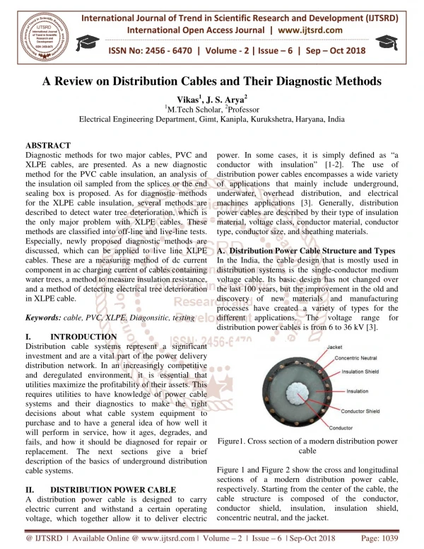
International Journal of Trend in International Open Access Journal International Open Access Journal | www.ijtsrd.com International Journal of Trend in Scientific Research and Development (IJTSRD) Research and Development (IJTSRD) www.ijtsrd.com ISSN No: 2456 ISSN No: 2456 - 6470 | Volume - 2 | Issue – 6 | Sep 6 | Sep – Oct 2018 A Review on Distribution Distribution Cables and Their Diagnostic Methods Vikas1, J. S. Arya2 1M.Tech Scholar, 2Professor Diagnostic Methods Electrical Engineering Department Electrical Engineering Department, Gimt,Kanipla, Kurukshetra,Haryana Haryana, India ABSTRACT Diagnostic methods for two major cables, PVC and XLPE cables, are presented. As a new diagnostic method for the PVC cable insulation, an analysis of the insulation oil sampled from the splices or the end sealing box is proposed. As for diagnostic methods for the XLPE cable insulation, several methods are described to detect water tree deterioration, which is the only major problem with XLPE cables. These methods are classified into off-line and live Especially, newly proposed diagnostic methods discussed, which can be applied to live cables. These are a measuring method of dc current component in ac charging current of cables containing water trees, a method to measure insulation resistance, and a method of detecting electrical tree in XLPE cable. Keywords: cable, PVC, XLPE, Diagonsitic, testing I. INTRODUCTION Distribution cable systems represent a significant investment and are a vital part of the power delivery distribution network. In an increasingly competitive and deregulated environment, it is essential that utilities maximize the profitability of their assets. This requires utilities to have knowledge of power cable systems and their diagnostics to make the right decisions about what cable system equipment to purchase and to have a general idea of how well it will perform in service, how it ages, degrades, and fails, and how it should be diagnosed for repair or replacement. The next sections gi description of the basics of underground distribution cable systems. II. DISTRIBUTION POWER CABLE A distribution power cable is designed to carry electric current and withstand a certain operating voltage, which together allow it to deliver electri voltage, which together allow it to deliver electric power. In some cases, it is simply defined as “a conductor with insulation” [1 distribution power cables encompasses a wide variety of applications that mainly include underground, underwater, overhead distribution, and electrical machines applications [3]. Generally, distribution power cables are described by their type of insulation material, voltage class, conductor material, conductor type, conductor size, and sheathing materials. A.Distribution Power Cable Structure and Types In the India, the cable design that is mostly used in distribution systems is the single voltage cable. Its basic design has not changed over the last 100 years, but the improvement in the old and discovery of new materials and manufacturi processes have created a variety of types for the different applications. The voltage range for distribution power cables is from 6 to 36 kV [3]. Diagnostic methods for two major cables, PVC and XLPE cables, are presented. As a new diagnostic method for the PVC cable insulation, an analysis of the insulation oil sampled from the splices or the end sealing box is proposed. As for diagnostic methods or the XLPE cable insulation, several methods are described to detect water tree deterioration, which is the only major problem with XLPE cables. These power. In some cases, it is simply defined as “a conductor with insulation” [1-2]. The use of distribution power cables encompasses a wide variety of applications that mainly include underground, underwater, overhead distribution, and electrical applications [3]. Generally, distribution power cables are described by their type of insulation material, voltage class, conductor material, conductor type, conductor size, and sheathing materials. line and live-line tests. Especially, newly proposed diagnostic methods are discussed, which can be applied to live line XLPE cables. These are a measuring method of dc current component in ac charging current of cables containing water trees, a method to measure insulation resistance, and a method of detecting electrical tree deterioration Distribution Power Cable Structure and Types In the India, the cable design that is mostly used in distribution systems is the single-conductor medium voltage cable. Its basic design has not changed over the last 100 years, but the improvement in the old and discovery of new materials and manufacturing processes have created a variety of types for the different applications. The voltage range for distribution power cables is from 6 to 36 kV [3]. cable, PVC, XLPE, Diagonsitic, testing Distribution cable systems represent a significant power delivery distribution network. In an increasingly competitive and deregulated environment, it is essential that utilities maximize the profitability of their assets. This requires utilities to have knowledge of power cable cs to make the right decisions about what cable system equipment to purchase and to have a general idea of how well it will perform in service, how it ages, degrades, and fails, and how it should be diagnosed for repair or replacement. The next sections give a brief description of the basics of underground distribution Figure1. Cross section of a modern distribution power cable Figure 1 and Figure 2 show the cross and lo sections of a modern distribution power cable, respectively. Starting from the center of the cable, the cable structure is composed of the conductor, conductor shield, insulation, insulation shield, concentric neutral, and the jacket. concentric neutral, and the jacket. modern distribution power Figure 1 and Figure 2 show the cross and longitudinal sections of a modern distribution power cable, respectively. Starting from the center of the cable, the cable structure is composed of the conductor, conductor shield, insulation, insulation shield, ON POWER CABLE A distribution power cable is designed to carry electric current and withstand a certain operating @ IJTSRD | Available Online @ www.ijtsrd.com www.ijtsrd.com | Volume – 2 | Issue – 6 | Sep-Oct 2018 Oct 2018 Page: 1039
International Journal of Trend in Scientific Research and Development (IJTSRD) ISSN: 2456 International Journal of Trend in Scientific Research and Development (IJTSRD) ISSN: 2456 International Journal of Trend in Scientific Research and Development (IJTSRD) ISSN: 2456-6470 commonly known as 4/0, and the smallest is 36, pproximately 0.0050 in. in diameter. When the conductor size is greater than 4/0 AWG, it is given by the cross sectional area in thousands of circular mils (MCM), or kcmils. In some situations, MCM is used instead of kcmils. One circular mil (cmil) is ned as the area of a solid conductor having a diameter of one mil (one thousand of an inch) [1]. In addition, solid conductor types are found only up to commonly known as 4/0, and the smallest is 36, which is approximately 0.0050 in. in diameter. When the conductor size is greater than 4/0 AWG, it is given by the cross sectional area in thousands of circular mils (MCM), or kcmils. In some situations, MCM is used instead of kcmils. One circular mil (cmil) is defined as the area of a solid conductor having a diameter of one mil (one thousand of an inch) [1]. In addition, solid conductor types are found only up to 1/0 AWG size. C.Conductor Shield The main function of the conductor shield, or conductor screen, is to provide for a smooth interface between the conductor and the insulation. The smooth interface between the conductor shield and insulation avoids the presence of sharp points (known as protrusions) that could impose high the insulation. The conductor shield and the insulation are chemically bonded. If the conductor shield is not present, electric field lines are more concentrated in the sharper edges around the outside perimeter of the conductor. As a result, high- created between the conductor and the insulation interface. This decreases the life of the cable, as its eventual failure will likely be caused by this increased voltage stress. The conductor shield is made of a semi conductive material. The semi conductive specially designed with about 30% to 40% carbon black to meet the required conductivity [3] such that the conductor shield and the conductor are at the same potential when the cable is energized. D.Insulation The insulation is capable of withst operating voltage at the operating rated temperature, typically from 75° C to 90° C [3, 5]. The insulation can be classified as laminated or extruded insulation. The insulation should be clean there should be smooth interfaces with the conductor shield to avoid high electrical stresses that could cause early insulation failure. The first insulation type, laminated insulation, is represented exclusively by Paper Insulated Lead Covered (PILC) cables. Layers of impregnated paper are placed on top of one another to create the cable insulation. Impregnated paper is the oldest and the most widely used material. Generally, the paper is impregnated with oil or gel that has dielectric properties suitable for insulation applications. As the impregnator needs to be contained within the insulation, the cable typically has a lead sheath. This type of cable has been used for a lead sheath. This type of cable has been used for Figure2. Longitudinal section of a modern distribution power cable B.Conductor The main function of the conductor is to carry the electric current. Typically, it is made of copper or aluminum alloys and can be solid or stranded. A stranded conductor has more flexibility compared to a solid conductor; the wire strands may be filled with a resin to prevent water ingress and then it is called a “filled” conductor. Unfilled conductors, on the other hand, simply do not contain resin. It will be seen later that water plays an important role in cable degradation and failure mechanisms. Copper alloys are about three times denser than aluminum alloys. Therefore, copper conductors are three times heavier than aluminum conductors. Lighter cables are preferable for installation. Nevertheless, because of the electrical conductivity of both materials and for a given current specification, a copper conductor can be two sizes smaller than an aluminum conductor. Thus, sizing and material selection of the conductor are not easy tasks since the criteria also depend on voltage drop along the cable, characteristics of the insulation material, flexibility, cable design, installation method, weight, and cost. In some situations, the conductor concentric round, but in other situations th is compressed with the idea of providing an even smoother interface at the outer surface of the conductor, see Figure 3. . Longitudinal section of a modern distribution The main function of the conductor is to carry the electric current. Typically, it is made of copper or aluminum alloys and can be solid or stranded. A ibility compared to a The main function of the conductor shield, or rovide for a smooth interface between the conductor and the insulation. The smooth interface between the conductor shield and insulation avoids the presence of sharp points (known as protrusions) that could impose high-voltage stress to conductor shield and the insulation are chemically bonded. If the conductor shield is not present, electric field lines are more concentrated in the sharper edges around the outside perimeter of the solid conductor; the wire strands may be filled with a resin to prevent water ingress and then it is called a “filled” conductor. Unfilled conductors, on the other hand, simply do not contain resin. It will be seen later ays an important role in cable degradation and failure mechanisms. Copper alloys are about three times denser than aluminum alloys. Therefore, copper conductors are three times heavier than aluminum conductors. Lighter cables are preferable for n. Nevertheless, because of the electrical conductivity of both materials and for a given current specification, a copper conductor can be two sizes smaller than an aluminum conductor. Thus, sizing and material selection of the conductor are not easy tasks since the criteria also depend on voltage drop along the cable, characteristics of the insulation material, flexibility, cable design, installation method, weight, and cost. In some situations, the conductors is concentric round, but in other situations the conductor is compressed with the idea of providing an even smoother interface at the outer surface of the -voltage stress areas are eated between the conductor and the insulation interface. This decreases the life of the cable, as its eventual failure will likely be caused by this increased voltage stress. The conductor shield is made of a semi conductive material. The semi conductive material is specially designed with about 30% to 40% carbon black to meet the required conductivity [3] such that the conductor shield and the conductor are at the same potential when the cable is energized. The insulation is capable of withstanding the operating voltage at the operating rated temperature, typically from 75° C to 90° C [3, 5]. The insulation can be classified as laminated or extruded insulation. The insulation should be clean there should be smooth interfaces with the conductor shield and insulation shield to avoid high electrical stresses that could cause early insulation failure. The first insulation type, laminated insulation, is represented exclusively by Paper Insulated Lead Covered (PILC) cables. Layers r are placed on top of one another to create the cable insulation. Impregnated paper is the oldest and the most widely used material. Generally, the paper is impregnated with oil or gel that has dielectric properties suitable for insulation s the impregnator needs to be contained within the insulation, the cable typically has Figure3. Concentric round and compressed round conductors The conductor size is given by the conductor cross sectional area. In India, the conductor size is defined by the Bureau of Indian Standards (BIS). The gauge is formed by a geometric progression between two consecutive diameters. The largest AWG size is 0000, consecutive diameters. The largest AWG size is 0000, 3. Concentric round and compressed round The conductor size is given by the conductor cross area. In India, the conductor size is defined by the Bureau of Indian Standards (BIS). The gauge is formed by a geometric progression between two @ IJTSRD | Available Online @ www.ijtsrd.com www.ijtsrd.com | Volume – 2 | Issue – 6 | Sep-Oct 2018 Oct 2018 Page: 1040
International Journal of Trend in Scientific Research and Development (IJTSRD) ISSN: 2456 International Journal of Trend in Scientific Research and Development (IJTSRD) ISSN: 2456 International Journal of Trend in Scientific Research and Development (IJTSRD) ISSN: 2456-6470 over a 100 years and has seen extensive mature testing and evaluation procedures developed. Even with these procedures in place, the manufacturing and installing of paper cable still requires significant skill. The use of PILC cables is declining. This situation is mainly due to environmental concerns with the lead cover and the impregnators [3]. In addition, paper cables have higher insulation losses and installation and maintenance costs than extruded insulation cables [5]. In fact, there has been a closure of paper impregnated manufacturing plants in the last few decades, which in some situations makes PILC cable even difficult to find for new installations, maintenance, or repairs [3]. The second insulation type, extruded insulation, can be classified as thermoplastic or thermo thermoplastic melts at a certain temperature and freezes to a brittle and glassy state when the temperature is decreased sufficiently. Thermoplastic insulation includes polyethylene (PE), which is divided into Low Molecular Weight PE (LMWPE) also known as Low Density PE (LDPE), and High Molecular Weight PE (HMWPE) also known as H Density (HDPE). On the other hand, a thermo polymer that cures to a more durable form because of curing. The curing converts the resin into a plastic or rubber using a cross-linking process into a rigid three dimensional molecular structure. The cross process creates a molecule with a larger molecular weight, resulting in a material with a higher melting point. In general, a thermo set is stronger than thermoplastic because of the three molecular structure. Thermo set materials withstand higher temperatures and are not recyclable as are thermoplastics [3]. Thermo set includes Cross-linked PE (XLPE), Water Tree Retardant XLPE (WTRXLPE) also known as Tree Retardant XLPE (TRXLPE), and Ethylene Propylene Rubber (EPR). These are the insulations in popular use today. E.Insulation Shield The insulation shield, or insulation screen, serves the same function as the conductor shield and provides a smooth interface between the insulation and the concentric neutral. If the insulation shield is not present, electric field lines will appear around outside the cable insulation. The insulation shield assures that the voltage outside the cable is at ground potential. In India, the insulation shield and the insulation are not chemically bonded; in this case, the insulation shield is called a strippable shield. Strippable shields is called a strippable shield. Strippable shields over a 100 years and has seen extensive mature testing and evaluation procedures developed. Even s in place, the manufacturing and installing of paper cable still requires significant skill. The use of PILC cables is declining. This situation is mainly due to environmental concerns with the lead cover and the impregnators [3]. In addition, paper s have higher insulation losses and installation and maintenance costs than extruded insulation cables [5]. In fact, there has been a closure of paper impregnated manufacturing plants in the last few decades, which in some situations makes PILC cable difficult to find for new installations, maintenance, or repairs [3]. The second insulation type, extruded insulation, can be classified as facilitate the cutback for terminating and splicing the cable [3]. 12 The group of the conductor, conductor shield, insulation, and insulation shield is known as the cable core. The cable core is designed to keep the electric field inside the cable insulation and carry the electric current while dissipating the heat generated by the conductor during the useful life of the cable facilitate the cutback for terminating and splicing the cable [3]. 12 The group of the conductor, conductor shield, insulation, and insulation shield is known the cable core. The cable core is designed to keep the electric field inside the cable insulation and carry the electric current while dissipating the heat generated by the conductor during the useful life of the cable [3]. F.Concentric Neutral The concentric neutral is placed over the insulation shield to keep the outer part of the cable core at ground potential, thus providing protection against accidental contact. It is also designed to carry fault currents, stray currents, charging currents, and imbalanced currents. The concentric neutral can be replaced by a metallic sheath to accomplish the same function. In this situation, the cable is said to be completely shielded. Generally, the concentric neutral or metallic sheath have been made of lead, alumin or copper in a variety of designs that include thin tapes, round wires, and solid or corrugated extruded tubes [3]. Corrosion is a problem for concentric neutrals and metallic sheaths and may occur at the interface between the metal and its surrounding corrosion is accelerated by the presence of water and the related pH of the soil [2]. The concentric neutral or the metallic sheath must be continuous along the cable length and have good contact with the insulation shield to guarantee that the oute core is at ground potential. The lack of sufficient contact can generate a voltage gradient between the insulation shield and concentric neutral or metallic sheath. In this situation, electrical discharges could be generated and cause erosion of the insulation screen and subsequently the insulation. Eventually, this will lead to a cable failure [3]. G.Jacket The jacket, also known as the over protective covering that may also provide additional insulation. The protection mechanical, thermal, or chemical stresses. Therefore, it reduces the concentric neutral or metallic sheath corrosion as well as the moisture ingress to the cable. It could also be designed to hold a metallic armor, wires, or tapes [2-3], enhancing even more the level of protection. Typical Polyvinylchloride (PVC), chlorosulfonated PE, PE, LDPE, Linear Low Density PE (LLDPE), Medium Density PE (MDPE), HDPE, and nylon [2 Variations on the designs previously described are Variations on the designs previously described are ntric neutral is placed over the insulation shield to keep the outer part of the cable core at ground potential, thus providing protection against accidental contact. It is also designed to carry fault currents, stray currents, charging currents, and anced currents. The concentric neutral can be replaced by a metallic sheath to accomplish the same function. In this situation, the cable is said to be completely shielded. Generally, the concentric neutral or metallic sheath have been made of lead, aluminum, or copper in a variety of designs that include thin tapes, round wires, and solid or corrugated extruded tubes [3]. Corrosion is a problem for concentric neutrals and metallic sheaths and may occur at the interface between the metal and its surroundings. The corrosion is accelerated by the presence of water and the related pH of the soil [2]. The concentric neutral or the metallic sheath must be continuous along the cable length and have good contact with the insulation shield to guarantee that the outer area of the cable core is at ground potential. The lack of sufficient contact can generate a voltage gradient between the insulation shield and concentric neutral or metallic sheath. In this situation, electrical discharges could be rosion of the insulation screen and subsequently the insulation. Eventually, this will set set insulation. insulation. A A thermoplastic melts at a certain temperature and lassy state when the temperature is decreased sufficiently. Thermoplastic insulation includes polyethylene (PE), which is divided into Low Molecular Weight PE (LMWPE) also known as Low Density PE (LDPE), and High Molecular Weight PE (HMWPE) also known as High Density (HDPE). On the other hand, a thermo set is a polymer that cures to a more durable form because of curing. The curing converts the resin into a plastic or linking process into a rigid three- e cross-linking process creates a molecule with a larger molecular weight, resulting in a material with a higher melting set is stronger than thermoplastic because of the three-dimensional materials can withstand higher temperatures and are not recyclable Thermo set insulation linked PE (XLPE), Water Tree Retardant XLPE (WTRXLPE) also known as Tree Retardant XLPE (TRXLPE), and Ethylene Propylene These are the insulations in popular The jacket, also known as the over-sheath, is a protective covering that may also provide additional insulation. The protection mechanical, thermal, or chemical stresses. Therefore, it reduces the concentric neutral or metallic sheath corrosion as well as the moisture ingress to the cable. It could also be designed to hold a metallic armor, coul could be against The insulation shield, or insulation screen, serves the same function as the conductor shield and provides a smooth interface between the insulation and the lation shield is not present, electric field lines will appear around outside the cable insulation. The insulation shield assures that the voltage outside the cable is at ground potential. In India, the insulation shield and the insulation are not ly bonded; in this case, the insulation shield cing even more the level Typical of Polyvinylchloride (PVC), chlorosulfonated PE, PE, LDPE, Linear Low Density PE (LLDPE), Medium Density PE (MDPE), HDPE, and nylon [2-3]. protection. materials materials include include @ IJTSRD | Available Online @ www.ijtsrd.com www.ijtsrd.com | Volume – 2 | Issue – 6 | Sep-Oct 2018 Oct 2018 Page: 1041
International Journal of Trend in Scientific Research and Development (IJTSRD) ISSN: 2456 International Journal of Trend in Scientific Research and Development (IJTSRD) ISSN: 2456 International Journal of Trend in Scientific Research and Development (IJTSRD) ISSN: 2456-6470 available and are shown in Figure 4. They include concentric neutral without a jacket, metal clad cable (TECK cable) mainly used in mining and industrial applications, shielded cables with copper tape shields, and PILC cable [4] ilable and are shown in Figure 4. They include concentric neutral without a jacket, metal clad cable (TECK cable) mainly used in mining and industrial applications, shielded cables with copper tape shields, process which changes the molecular structure of the polymer chains so that they are more tightly bound cross linking is done either by al means or physical means. Chemical cross linking involves the addition of chemicals or initiators such as silane or peroxide to generate free radicals linking. Physical cross linking involves subjecting the polymer to a high energy energy electron or microwave process which changes the molecular structure of the polymer chains so that they are more tightly bound together and this cross linking chemical means or physical means. Chemical cross linking involves the addition of chemicals or initiators such as silane or peroxide to generate free radicals which form the cross linking. Physical cross involves subjecting the polymer to a high energy source such as high-energy electron or microwave radiation. Polyethylene (PE) material itself has excellent dielectric strength, high insulation resistance, and a low dissipation factor at all frequencies making it an ideal insulator; however it is limited in range. Cross-linking the PE to become XLPE increases the temperature range of the insulation whilst maintaining the electrical properties. XLPE is suitable for voltage ranges from low to extra high voltage, surpassing other insulation mater such as PVC, Ethylene Propylene Rubber (EPR) and silicone rubbers. Cross-linking the polyethylene also enhances the chemical and oil resistance at elevated temperatures and makes it suitable for use as a Low Smoke Zero Halogen material. The mechanical properties of the XLPE are superior to much other insulation, offering greater tensile strength, elongation and impact resistances. The addition of carbon black can be used to further enhance hot deformation and cut through resistance. The XLPE insulation will not melt or drip, even at the temperatures of soldering irons, and it has increased flow resistance and improved ageing characteristics. Improved water-tree resistance is another benefit of XLPE insulation for LV cables and MV cables over PE insulations. Water treeing is a defect which is the result of imperfections in the insulation where fracture lines occur and grow in the direction of the electric field, increasing with electrical stress. It should be noted that this effect is not limited to P Insulation failure of cables causes stoppage of electric service and requires much repair work. Many utilities are therefore very interested in practical and easy methods of diagnosing precisely the degree of deterioration of installed cable in cables are classified into two major groups: oil impregnated paper, and cross insulated power cables. Diagnostic methods for these two cables, proposed in India, are discussed here. Polyethylene (PE) material itself has excellent dielectric strength, high insulation resistance, and a low dissipation factor at all frequencies making it an however it is limited in its temperature linking the PE to become XLPE increases the temperature range of the insulation whilst maintaining the electrical properties. . Figure4. Different cable types ypes III. DISTRIBUTION POWER CABLE AND ACCESSORIES Generally, a single length of cable is not long enough to cover the distance between points to which it is desired to distribute the electric power and therefore multiple cable lengths are cascade connected. cable lengths are connected by joints or splices. At both ends of the cable lengths, a termination is used to make the transition from the underground to the overhead part of the distribution system or to a distribution transformer. When the transition between the cable and a transformer the termination is usually known as an elbow termination or, simply, elbow. The joints and terminations are commonly known as accessories of the power cable system. The group of cable lengths, joints, and termination together referred to as a section of the power distribution cable system or simply cable segment. Cable accessories play an important role in the power cable system insulation performance. As part of the power distribution cable system, they can also failure. Therefore, the quality of cable accessories should be comparable to the quality of the cable itself such that the cable segment experiences uniform performance over time. When a segment contains more than one cable insulation type and one type of cable joints and terminations, the segment is said to be a hybrid. IV. DIFFERENCE BETWEEN XLPE AND PVC CABLES XLPE or Cross-linked polyethylene is a insulation material. Cross linking polymers is a DISTRIBUTION POWER CABLE AND XLPE is suitable for voltage ranges from low to extra high voltage, surpassing other insulation materials such as PVC, Ethylene Propylene Rubber (EPR) and linking the polyethylene also enhances the chemical and oil resistance at elevated temperatures and makes it suitable for use as a Low Smoke Zero Halogen material. Generally, a single length of cable is not long enough to cover the distance between points to which it is desired to distribute the electric power and therefore multiple cable lengths are cascade connected. The cable lengths are connected by joints or splices. At both ends of the cable lengths, a termination is used to make the transition from the underground to the overhead part of the distribution system or to a distribution transformer. When the transition is between the cable and a transformer the termination is usually known as an elbow termination or, simply, elbow. The joints and terminations are commonly known as accessories of the power cable system. The group of cable lengths, joints, and terminations are together referred to as a section of the power distribution cable system or simply cable segment. Cable accessories play an important role in the power cable system insulation performance. As part of the power distribution cable system, they can also lead to failure. Therefore, the quality of cable accessories should be comparable to the quality of the cable itself such that the cable segment experiences uniform performance over time. When a segment contains more than one cable insulation type and one or more type of cable joints and terminations, the segment is cal properties of the XLPE are superior , offering greater tensile strength, elongation and impact resistances. The addition of carbon black can be used to further enhance hot deformation and cut through resistance. tion will not melt or drip, even at the temperatures of soldering irons, and it has increased flow resistance and improved ageing characteristics. tree resistance is another benefit of XLPE insulation for LV cables and MV cables over lations. Water treeing is a defect which is the result of imperfections in the insulation where fracture lines occur and grow in the direction of the electric field, increasing with electrical stress. It should be noted that this effect is not limited to PE materials. Insulation failure of cables causes stoppage of electric service and requires much repair work. Many utilities are therefore very interested in practical and easy methods of diagnosing precisely the degree of deterioration of installed cable insulation. Power cables are classified into two major groups: oil- impregnated paper, and cross-linked polyethylene insulated power cables. Diagnostic methods for these DIFFERENCE BETWEEN XLPE AND linked polyethylene is a Thermo set linking polymers is a , are discussed here. @ IJTSRD | Available Online @ www.ijtsrd.com www.ijtsrd.com | Volume – 2 | Issue – 6 | Sep-Oct 2018 Oct 2018 Page: 1042
International Journal of Trend in Scientific Research and Development (IJTSRD) ISSN: 2456 International Journal of Trend in Scientific Research and Development (IJTSRD) ISSN: 2456 International Journal of Trend in Scientific Research and Development (IJTSRD) ISSN: 2456-6470 V. DIAGNOSTIC IMPREGNATED PAPER-INNSULATED POWER CABLES Self-contained oil-filled (OF) cables are based on a complex insulation system composed of insulating paper and insulation oil. For OF cables which have no voids in normal operating condition, the insulation deterioration may be almost left out of consideration. Generally, a check is made for monitoring the change of oil pressure of a cable system including accessories, which keeps the cable insulation system in good condition. Recently, for the purpose of detecting the deterioration of insulation oil caused by poor splices and end sealing boxes, an analysis of the insulation oil sampled from the splice or the end sealing box is proposed as a diagnostic method for the OF cable insulation [1]. Corona discharge or arc can be detected if gases are in the insulation oil. This analysis plays an important role in maintaining transformers. For the detection of deterioration of the insulating oil, measurements are made of dielectric dissipation factor, and specific volume resistivity, in addition to measurements of moisture content and gas analysis. In these measurements, it is very important to sample the insulation oil without contaminating it. For this purpose, the sampling of insulation oil from splices or end sealing box is conducted carefully by using a syringe. Table 1 shows the tentative criteria for diagnosis of insulation oil. A.Maintaining the Integrity of the Specifications The template is used to format your paper and style the text. All margins, column widths, line spaces, and text fonts are prescribed; please do not alter them. You may note peculiarities. For example, the head margin in this template measures proportionately more than is customary. This measurement and others are deliberate, using specifications that anticipate your paper as one part of the entire proceedings, and not as an independent document. Please do not revise any of the current designations. VI. DIAGNOSTIC METHOD FOR XLPE INSULATED POWER CABLES XLPE cables have been used in underground distribution systems for almost 30 years, and their use is still increasing because of their excellent dielectric properties and easy handling. The only major problem with XLPE cables is deterioration by water trees, and it sometimes is the main cause of insulation failures in XLPE cables in long service. Up to the present, several methods have been proposed in Japan to detect water tree deterioration in addition to detect water tree deterioration in addition to DIAGNOSTIC METHOD METHOD FOR FOR INNSULATED OIL OIL- conventional methods such as measuring the dc leakage current or the dielectric dissipation factor. These methods are classified into off-line and live- conventional methods such as measuring the dc leakage current or the dielectr These methods are classified into off line tests. A.OFF-LINE METHOD Electrical breakdown of the polymeric insulations occurs after initiation of electrical trees. The inception and propagation of electrical trees are clo to the electrical charge injected and accumulated in the insulation. Therefore, the measurement of electrical charges in the insulation will be a useful method to predict pre-breakdown of the insulation and to diagnose the degree of insulation Recently, several such methods to detect water tree deterioration are proposed. It is presumed that charge is injected from the tips of water trees. Method for Measuring Residual Voltage The cable is grounded for 10 s after dc voltage (1 kV then released from ground. The voltage rise on the cable conductor (residual voltage) after10 min. is measured [2]. B.METHOD FOR MEASURING ABSORPTION CURRENT During Discharge the dc voltage is applied and the discharge current (absorption current) is measured after shorting the conductor to the outer shield for a few seconds in order to avoid the influence of capacitive charging currents [3]. Absorption charge Q (integrated absorption current) divided by the capacitance C of the cable (Q/C) is deterioration. The relation between the ac breakdown strength and the index Q/C. Method for Measuring Potential Decay after charging rate is measured after dc voltage application and removal [4]. It depends on the degree of deterioration of the insulation. Measurement of dc Transient Response Current the dc transient current is measured in the absence of the absorption current application [5] C.LIVE-LINE METHOD New diagnostic methods have been pro can be applied to live-line XLPE cables. Measuring dc Component in ac Charging Current The existence of a dc component was found in the ac charging current of XLPE cables deteriorated by water trees, through the investigation of the electric c phenomenon of XLPE cables with water trees [6]. The dc component was found to be a sign of the existence of water trees. filled (OF) cables are based on a complex insulation system composed of insulating paper and insulation oil. For OF cables which have no ion, the insulation Electrical breakdown of the polymeric insulations occurs after initiation of electrical trees. The inception and propagation of electrical trees are closely related to the electrical charge injected and accumulated in . Therefore, the measurement of electrical charges in the insulation will be a useful breakdown of the insulation and to diagnose the degree of insulation deterioration. Recently, several such methods to detect water tree deterioration are proposed. It is presumed that charge is injected from the tips of water trees. Method for Measuring Residual Voltage The cable is grounded for 10 s after dc voltage (1 kV/ mm) application and then released from ground. The voltage rise on the cable conductor (residual voltage) after10 min. is deterioration may be almost left out of consideration. Generally, a check is made for monitoring the change of oil pressure of a cable system including accessories, which keeps the cable insulation system r the purpose of detecting the deterioration of insulation oil caused by poor splices and end sealing boxes, an analysis of the insulation oil sampled from the splice or the end sealing box is proposed as a diagnostic method for the . Corona discharge or arc can be detected if gases are in the insulation oil. This analysis plays an important role in maintaining transformers. For the detection of deterioration of the insulating oil, measurements are made of dielectric r, and specific volume resistivity, in ture content and gas METHOD FOR MEASURING ABSORPTION In these measurements, it is very important to sample the insulation oil without contaminating it. For this purpose, the sampling of insulation oil from plices or end sealing box is conducted carefully by using a syringe. Table 1 shows the tentative criteria he dc voltage is applied and the ion current) is measured after shorting the conductor to the outer shield for a few seconds in order to avoid the influence of capacitive charging currents [3]. Absorption charge Q (integrated absorption current) divided by the Maintaining the Integrity of the Specifications The template is used to format your paper and style gins, column widths, line spaces, and text fonts are prescribed; please do not alter them. You may note peculiarities. For example, the head margin in this template measures proportionately more than is customary. This measurement and others , using specifications that anticipate your paper as one part of the entire proceedings, and not as an independent document. Please do not revise any of Q/C) is the index of the he relation between the ac breakdown strength and the index Q/C. Method for Measuring charging the voltage discharge rate is measured after dc voltage application and the degree of deterioration of the insulation. Measurement of dc Transient dc transient current is measured in the absence of the absorption current during voltage DIAGNOSTIC METHOD FOR XLPE INSULATED POWER CABLES New diagnostic methods have been proposed, which line XLPE cables. Measuring dc Component in ac Charging Current The existence of a dc component was found in the ac charging current of XLPE cables deteriorated by water trees, through the investigation of the electric conduction phenomenon of XLPE cables with water trees [6]. The dc component was found to be a sign of the in underground 0 years, and their use is still increasing because of their excellent dielectric properties and easy handling. The only major problem XLPE cables is deterioration by water trees, and main cause of insulation failures in XLPE cables in long service. Up to the present, several methods have been proposed in Japan to @ IJTSRD | Available Online @ www.ijtsrd.com www.ijtsrd.com | Volume – 2 | Issue – 6 | Sep-Oct 2018 Oct 2018 Page: 1043
International Journal of Trend in Scientific Research and Development (IJTSRD) ISSN: 2456 International Journal of Trend in Scientific Research and Development (IJTSRD) ISSN: 2456 International Journal of Trend in Scientific Research and Development (IJTSRD) ISSN: 2456-6470 VII. Construction and different parts of power cables has been studied. The distribution cable been studied in detail. For diagnostic of different faults in the power cables the test which have to be performed are explained in detail. This will help in detection and type of fault in the power cable. REFERENCES 1.A. Bulinski, E. So, S. Bamji, J. Densley, G. Hoff, H.-G. Krantz, M. Mashikian, and P. Werelius, Panel on diagnostic measurement techniques for power cables, presented at the IEEE/PES T&D Conf., New Orleans, LA, USA, April 11 2.Bahder, C. Katz, J. Lawson, and W. Vahlstrom, “Electrical and electrochemical polyethylene and crosslinked cables,” IEEE Trans. Power App. and Syst., vol. PAS 93, pp. 979– 990, May/June 1974. 3.S. Bamji, A. Bulinski, J. Densley, A. Garton, and N. Shimizu, “Water treeing in polymeric insulation,” Congres International des Grands Reseaux Electriques (C 1984. 4.S. Hvidsten, E. Ildstad, and J. Sletbak, “Understanding water treeing mechanisms in the development of diagnostic test methods,” Trans. Dielect. Electric. Insulation, vol. 754–760, Oct. 1998. 5.Kirkland, R. Thiede, and R. Reitz, “Evaluating the service degradation of insulated power cables,” IEEE Trans.Power App.Syst., vol. PAS 101 2128–2136, Jul. 1982. 6.S. Bamji, A. Bulinski, and J. Densley, “Final breakdown mechanism of water treeing,” Annual Report of the Conference on Electrical Insulation and Dielectric Phenomena, 1991, pp. 298 7.S. Boggs, J. Densley, and J. Kuang, “Mechanism for conversion of water trees to under impulse conditions,” IEEE Trans. Power Delivery, vol. PD-13, pp. 310 8.M. Mashikian, “Preventive maintenance testing of shielded power cable systems,” IEEE Trans. Ind. Applicat., vol. 38, pp. 736– 9.“Estimation of life expectancy of XLPE cables: Aging of in-Situ tested cables,” Electric Power Research Institute (EPRI), Final Report 1001892, Dec. 2001, p. 5 Writer’s Handbook. Mill Valley, CA: University Science, 1989. Conclusions The measuring device is connected between one end of the metal shield of a cable and the ground. A switch is connected between the other ends of the metal shield for the purpose of disconnecting it from the ground during the measurement. In the dc component measurement (switch opened), a closed circuit is formed by connecting the grounding potential transformer, distribution line, cable under measurement, measuring device and ground in series. The Fig. 1 shows the measuring equipment. The device is composed of four main c device for protection against grounding fault, a low pass filter, a dc current meter, and a recor Device for dc component measurement. (a) device; (b) Low-pass filter; (c) dc current. results in the field and in the laboratory, meter; (d) Recorder. It has been found that the dc components have good correlations with the length of water trees, as well as with other insulation criteria such as ac breakdown Based on the data obtained in the field and laboratory voltage (Fig. 8) and dc leakage current. Partial discharges in the polymeric insulations often cause treeing breakdown which is one of the most harmful degradation modes. If it is possible to detect treeing inception or treeing in the earlier stages on site, many breakdown failures in XLPE insulation may be avoided. It has been reported that a partial discharge of more than 100 pC is detected when the length of an electrical tree reaches 0.5 mm in the insulation. In order to develop a prediction method of insulation breakdown by treeing, the relation between the partial discharge characteristics and treeing propagation length was investigated [8]. The maximum partial discharge magnitude (Qmax) is not always proportional to the tree length. The pattern change of ¢-q distribution (mean pulse height distribution as a function of applied voltage phase angle) is a significant measure to indicate tree propagation. In the pre-breakdown stage, the skewness S of the ¢-q distribution of positive and negative pulses becomes negative, and the pre breakdown stage is detected by estimating S values. convenient method of monitoring the S distribution. S values at each time are expressed by a point in the S-plane and consequently the breakdown stage is easily detected when the plot appears in quadrant 3 of the S-plane. This S-plane method can be a preliminary prediction method of the breakdown by treeing. measuring device is connected between one end of the metal shield of a cable and the ground. A Construction and different parts of power cables has been studied. The distribution cable accessory has been studied in detail. For diagnostic of different faults in the power cables the test which have to be performed are explained in detail. This will help in detection and type of fault in the power cable. n the other ends of the metal shield for the purpose of disconnecting it from the ground during the measurement. In the dc component measurement (switch opened), a closed circuit is formed by connecting the grounding e, cable under device and ground in series. shows the measuring equipment. The device is composed of four main components; a tion against grounding fault, a low- pass filter, a dc current meter, and a recorder. Fig. 1: Device for dc component measurement. (a) Safety pass filter; (c) dc current. From the Bulinski, E. So, S. Bamji, J. Densley, G. Hoff, G. Krantz, M. Mashikian, and P. Werelius, Panel on diagnostic measurement techniques for power cables, presented at the IEEE/PES T&D LA, USA, April 11-16, 1999. . Lawson, and W. Vahlstrom, “Electrical and electrochemical polyethylene and crosslinked cables,” IEEE Trans. Power App. and Syst., vol. 990, May/June 1974. S. Bamji, A. Bulinski, J. Densley, A. Garton, and zu, “Water treeing in polymeric insulation,” Congres International des Grands Reseaux Electriques (CIGRE), Paris, France, boratory, meter; (d) treeing polyethylene polyethylene treeing in in t has been found that the dc components gth of water trees, as well as with other insulation criteria such as ac breakdown Based on the data obtained in the field and ) and dc leakage current. Partial discharges in the polymeric insulations often which is one of the most modes. If it is possible to detect treeing inception or treeing in the earlier stages on site, many breakdown failures in XLPE insulation may be avoided. It has been reported that a partial n 100 pC is detected when the length of an electrical tree reaches 0.5 mm in the insulation. In order to develop a prediction method of insulation breakdown by treeing, the relation between the partial discharge characteristics and treeing th was investigated [8]. The maximum partial discharge magnitude (Qmax) is not always proportional to the tree length. The pattern q distribution (mean pulse height distribution as a function of applied voltage phase S. Hvidsten, E. Ildstad, and J. Sletbak, “Understanding water treeing mechanisms in the development of diagnostic test methods,” IEEE Trans. Dielect. Electric. Insulation, vol. 5, pp. Kirkland, R. Thiede, and R. Reitz, “Evaluating the service degradation of insulated power cables,” IEEE Trans.Power App.Syst., vol. PAS 101, pp. A. Bulinski, and J. Densley, “Final breakdown mechanism of water treeing,” Annual Report of the Conference on Electrical Insulation enomena, 1991, pp. 298–305. S. Boggs, J. Densley, and J. Kuang, “Mechanism for conversion of water trees to electrical trees under impulse conditions,” IEEE Trans. Power 13, pp. 310–315, Apr. 1998. M. Mashikian, “Preventive maintenance testing of shielded power cable systems,” IEEE Trans. Ind. sure to indicate tree breakdown stage, the q distribution of positive and negative pulses becomes negative, and the pre- breakdown stage is detected by estimating S values. A convenient method of monitoring the S value distribution. S values at each time are expressed by a plane and consequently the breakdown stage is easily detected when the plot appears in –743, May/June 2002. Estimation of life expectancy of XLPE-insulated Situ tested cables,” Electric Power Research Institute (EPRI), Final Report 1001892, Dec. 2001, p. 5-5, Palo Alto, CA. s Handbook. Mill Valley, CA: University plane method can be a preliminary prediction method of the insulation @ IJTSRD | Available Online @ www.ijtsrd.com www.ijtsrd.com | Volume – 2 | Issue – 6 | Sep-Oct 2018 Oct 2018 Page: 1044