Download
1 / 4
40 likes | 64 Views
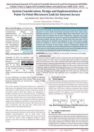
Microwave technology is extremely used for point to point communications because it is more easily focused into narrower beams than radio waves, allowing frequency use, it is available higher data transmission rates and antenna sizes are smaller than at lower frequencies. The main aim of this system is to provide internet access for rural area using ePMP Force 180 5GHz subscriber module. The two sites are 1.45 km away from each other. GPS is used to determine the latitude and longitude of two sites location. Google Earth Pro software is used to check for line of sight in choosing potential terminal site locations. In this system, system consideration, design and analysis of line of sight microwave link and hardware implementations are to be carried out. In the analysis, path profile, Fresnel zone, link budget and other parameters are implemented using the link planner software Lay Nandar Soe | Kyaw Thet Zaw | Wai Phyo Aung "System Consideration, Design and Implementation of Point-To-Point Microwave Link for Internet Access" Published in International Journal of Trend in Scientific Research and Development (ijtsrd), ISSN: 2456-6470, Volume-3 | Issue-5 , August 2019, URL: https://www.ijtsrd.com/papers/ijtsrd26769.pdf Paper URL: https://www.ijtsrd.com/engineering/electronics-and-communication-engineering/26769/system-consideration-design-and-implementation-of-point-to-point-microwave-link-for-internet-access/lay-nandar-soe<br>

E N D
International Journal of Trend in Scientific Research and Development (IJTSRD) Volume 3 Issue 5, August 2019 Available Online: www.ijtsrd.com e-ISSN: 2456 – 6470 System Consideration, Design and Implementation of Point-To-Point Microwave Link for Internet Access Lay Nandar Soe1, Kyaw Thet Zaw2, Wai Phyo Aung3 1Lecturer, 2Demonstrator, 3Professor 1, 2, 3Electronics & Communication Engineering, Department, TU, Loikaw, Myanmar How to cite this paper: Lay Nandar Soe | Kyaw Thet Zaw | Wai Phyo Aung "System Consideration, Implementation of Microwave Link for Internet Access" Published in International Journal of Trend in Scientific Research and Development (ijtsrd), ISSN: 2456- 6470, Volume-3 | Issue-5, August 2019, https://doi.org/10.31142/ijtsrd26769 Copyright © 2019 by author(s) and International Journal of Trend in Scientific Research and Development Journal. This is an Open Access article distributed under the terms of the Creative Commons Attribution License (CC (http://creativecommons.org/licenses/by /4.0) To use a frequency, a license should usually be obtained from the legal authorities of the country. There are also a few frequency bands that are “license-free” – mainly 2.4GHz, 5GHz and 24GHz. One of the reasons of microwave links are so adaptable is that they are broadband. They can move large amounts of information at high speeds. Another important quality of microwave links is that they require no equipment or facilities between the two terminal points, so installing a microwave link is often faster and less costly than a cable connection. Finally, they can be used almost anywhere, as long as the distance to be spanned is within the operating range of the equipment and there is clear path (that is, no solid obstacles) between the locations. Microwaves are also able to penetrate rain, fog, and snow, which mean bad weather doesn’t disrupt transmission. Microwave radio transmission is commonly used in point-to- point communication systems on the surface of the Earth, in satellite communications, and in deep space radio communications. Other parts of the microwave radio band are used for radars, radio navigation systems, sensor systems, and radio astronomy. (Mohamed Maher Hanafi, 2016) ABSTRACT Microwave technology is extremely used for point-to-point communications because it is more easily focused into narrower beams than radio waves, allowing frequency use, it is available higher data transmission rates and antenna sizes are smaller than at lower frequencies. The main aim of this system is to provide internet access for rural area using ePMP Force 180 5GHz subscriber module. The two sites are 1.45 km away from each other. GPS is used to determine the latitude and longitude of two sites location. Google Earth Pro software is used to check for line-of-sight in choosing potential terminal site locations. In this system, system consideration, design and analysis of line-of-sight microwave link and hardware implementations are to be carried out. In the analysis, path profile, Fresnel zone, link budget and other parameters are implemented using the link planner software. KEYWORDS: Microwave, ePMP Force, path profile, Fresnel zone, link budget 1.INTRODUCTION Microwave is a line-of-sight wireless communication technology that uses high frequency beams of radio waves to provide high speed wireless connections that can send receive voice, video, and data information. Microwave technology has been used for communication purposes since the 1940’s. A microwave link is a communications system that uses a beam of radio waves in the microwave frequency range to transmit information between two fixed locations on the earth. Microwave links range from 2.4GHz to 42GHz spectrum. The higher is the frequency, the higher the available capacity but at the same time, the effective range is lowered and the link would be more susceptible to rain or high humidity. 2.PROPOSED SYSTEM 2.1 Block diagram The block diagram of design and implementation of point-to- point microwave link for internet access is shown in figure. In this system, the signal from TP link router transfers to the transmitter module by using RJ 45 Ethernet cable. Cambium ePMP Force 180 5GHz is used as transmitter and receiver module. The signal is transmitted from transmitter module using microwave. The signals are received by Subscriber Module with Ethernet cable network. Design Point-To-Point and IJTSRD26769 pp.1695-1698, BY 4.0) Fig1. Block Diagram of Point to Point Microwave Link for Internet Access 2.1.1 Design Considerations A.Site selection Site selection is the process of choosing the optimal location for an anticipated use. Since microwave communication is a line-of-sight communication, the location of the transmitter and receiver sites is verifying that there are no natural and man-made obstructions between them. For site selection, Google Earth Pro software is used to check for line-of-sight in choosing potential terminal site locations. Google Earth @ IJTSRD | Unique Paper ID – IJTSRD26769 | Volume – 3 | Issue – 5 | July - August 2019 Page 1695
International Journal of Trend in Scientific Research and Development (IJTSRD) @ www.ijtsrd.com eISSN: 2456-6470 Pro is a virtual globe, map and geographical information program that map the Earth by the superimposition of images obtained from satellite imagery, aerial photography and geographic information system 3D globe. In this design, the receiver site is Taung Kwe Pagada, Loikaw (19.66750N, 097.20800E). After choosing the receiver site, the potential transmitter site is selected that are 1.45 km away from the receiver site. The transmitter is in EC department, TU loikaw (19.65450N, 097.20850E). obstructions (such as terrain, vegetation, buildings, etc.) penetrate the Fresnel zone, there will be signal attenuation. The Fresnel zone is computed along the path, usually for the distance of each of the terrain points, so the resolution of the computed and plotted Fresnel zone is comparable to the terrain data. The Nth Fresnel zone formula is a function of the wavelength (λ) and the distance along the path from each endpoint (D1 and D2): To maximize receiver strength, one needs to minimize the effect of obstruction loss by removing obstacles from the radio frequency line of sight (RF LOS). The strongest signals are on the direct line between transmitter and receiver and always lie in the first Fresnel zone. Fig2. Sites considerations using Google Earth Pro B.Calculation of Antennas’ Heights From above table, the AP site’s elevation high (e1), peak obstruction height (e0), and the SM site’s elevation high (e2) are 934.8, 911 and 902.9 meters above sea level respectively. d1=0.95km, d2=0.39km, k=4/3, F=5.8GHz, TG=10meters. Earth curvature, ??= Fig4. Fresnel zone results from Link planner E.LINK BUDGET CALCULATION The link budget is a calculation involving the gain and loss factors associated with the antennas, transmitters, transmission lines and propagation environment. Transmitter Power=30dBm Antenna Gain = 16dBi Branching loss Branching loss (LbR =2 dB) Radom loss Radom loss (LrR=0.5dB Miscellaneous losses Miscellaneous Loss (Lmisc=2dB) And Predicted received power, PRX PRX = RTX + GTX – LTX – FSL + GRX - LRX Where PRX is received signal power (dBm), PTX is the transmitter power (dBm), GTX is the transmitter antenna gain (dBi), LTX is the transmitter losses (dB), FSL is the free space loss (dB), GRX is the receiver antenna gain (dBi), LRX is the receiver losses (dB). Free space path loss FSPL = 92.4 + 20log?(???) + 20log?(??) = 92.4 + 20log5.8 + 20log1.335 = 110.27?? 3.IMPLEMENTATION In this part, figure (5) shows the configuration of TP-Link’s LAN and DHCP setting. ??.?? ??.???= ?.??×?.?? ??.??×?? ?= 0.022?? ??.?? First Fresnel zone, ??= 17.3? (?????)?(???)= 3.76? 60% clearance of first Fresnel zone, ??′ = 0.6 × 3.76? = 2.256? ??= ??+ ?? + ??= 921.02? Assume both AP site’s antenna height and SM site’s antenna height are the same, a=a1+a2. ??′ = [??(??− ?? ? The antenna height, a1=a2=11m. )] − ??+ ? + ?? Fig3.Consideration in antenna heights and beam width C.Antenna down tilt calculation The Antenna Down tilt and Coverage Calculator (aka Antenna Tilt Angle Calculator) is used to determine the approximate downward angle, measured in degrees, which the transmitting antenna is to be positioned for optimal signal strength and coverage. θ = tan??ℎ?− ℎ? ? D.Fresnel Zone Clearance The most common use of Fresnel zone information on a profile plot is to check for obstructions that penetrate the zone. Even though the path has clear line of sight, if = 1.39° Fig5. Configuration of TP Link Setting @ IJTSRD | Unique Paper ID – IJTSRD26769 | Volume – 3 | Issue – 5 | July - August 2019 Page 1696
International Journal of Trend in Scientific Research and Development (IJTSRD) @ www.ijtsrd.com eISSN: 2456-6470 And, it needs to configure the settings of ePMP force180 AP’s module. Fig8. Project Configuration 3.1 Transmission requirements: Maximum data rates > 155 Mbps Minimum required availability: 99.999% Ray parameters: 5.8GHz Modulation =Adaptive; BW=40MHz; TX power=26 dBm. In this part, table (1) shows the different parameters of obstacles, terrain heights and results of Fresnel zones and antenna heights Analysis and Results Fig6. Settings of ePMP force 180 AP’s Module Figure (7) shows the settings of SM module. Fig7. Configurations of SM Module Distance from Tx.d1 (km) 0 0.02896 0.05953 0.08850 0.11907 0.14803 0.17860 0.20756 0.23813 0.26709 0.29767 0.32663 0.35559 0.38616 0.41512 0.44569 0.47466 0.50523 0.53419 0.56476 0.59372 0.62429 0.65325 0.68222 0.71279 Terrain height (m) 934.8 934.9 932.4 932.6 933.6 933.2 932.1 930.6 928.6 926.3 923.3 920.2 917.9 915.8 914 913.5 914.1 913.6 911.3 908.1 907.7 907.9 906.3 905.5 906.5 Earth Curvature (m) 0 0.00223 0.00447 0.00649 0.00852 0.01034 0.01215 0.01377 0.01537 0.01679 0.01817 0.01938 0.02050 0.02156 0.02247 0.02333 0.02403 0.02467 0.02518 0.02560 0.02591 0.02612 0.02622 0.02622 0.02611 first fresnel clearan-ce F1 (m) 0 1.20916 1.71320 2.06492 2.36564 2.60611 2.82551 3.00763 3.17756 3.32054 3.45491 3.56823 3.66924 3.76359 3.84219 3.91448 3.97337 4.02588 4.06682 4.10102 4.12510 4.14189 4.14970 4.14970 4.14122 Total Extended high (m) 944.80000 946.11139 944.11767 944.67141 945.97416 945.81645 944.93766 943.62140 941.79293 939.63733 936.77308 933.78761 931.58973 929.58516 927.86466 927.43780 928.09740 927.65055 925.39200 922.22663 921.85101 922.06800 920.47592 919.67592 920.66733 Distance from Rx.d2 (km) Tree Obstacle Growth (m) 1 2 3 4 5 6 7 8 9 10 11 12 13 14 15 16 17 18 19 20 21 22 23 24 25 1.33547 1.30651 1.27594 1.24698 1.21640 1.18744 1.15687 1.12791 1.09734 1.06838 1.03781 1.00884 0.97988 0.94931 0.92035 0.88978 0.86082 0.83024 0.80128 0.77071 0.74175 0.71118 0.68222 0.65325 0.62268 10 10 10 10 10 10 10 10 10 10 10 10 10 10 10 10 10 10 10 10 10 10 10 10 10 @ IJTSRD | Unique Paper ID – IJTSRD26769 | Volume – 3 | Issue – 5 | July - August 2019 Page 1697
International Journal of Trend in Scientific Research and Development (IJTSRD) @ www.ijtsrd.com eISSN: 2456-6470 26 27 28 29 30 31 32 33 34 35 36 37 38 39 40 41 42 43 44 45 46 0.74175 0.77232 0.80128 0.83185 0.86082 0.89139 0.92035 0.94931 0.97988 1.00884 1.03941 1.06838 1.09895 1.12791 1.15848 1.18744 1.21801 1.24698 1.27594 1.30651 1.33547 0.59372 0.56315 0.53419 0.50362 0.47466 0.44408 0.41512 0.38616 0.35559 0.32663 0.29606 0.26709 0.23652 0.20756 0.17699 0.14803 0.11746 0.08849 0.05953 0.02896 0 908.5 907 903.7 903 906 908.1 909.5 911 909.6 907.6 907 907.2 907.5 907 905.7 904.8 903.6 901.5 901 903.4 902.9 Table1. Path Profile 0.02591 0.02558 0.02518 0.02464 0.02403 0.02329 0.02247 0.02156 0.02050 0.01938 0.01810 0.01679 0.01529 0.01377 0.01206 0.01034 0.00842 0.00649 0.00447 0.00223 0 10 10 10 10 10 10 10 10 10 10 10 10 10 10 10 10 10 10 10 10 10 4.12510 4.09945 4.06682 4.02336 3.97337 3.91093 3.84219 3.76359 3.66924 3.56823 3.44823 3.32054 3.16913 3.00763 2.81471 2.60611 2.35115 2.06492 1.71320 1.20916 0 922.65101 921.12504 917.79200 917.04800 919.99740 922.03422 923.36466 924.78516 923.28973 921.18761 920.46633 920.53733 920.68442 920.02140 918.52677 917.41645 915.95957 913.57141 912.71767 914.61139 912.90000 4.CONCLUSIONS Point to point microwave links are widely used as a cost effective alternative to fiber optic cabling for interconnecting the network of two sites with distances of few hundred meters and up to 50 km or more. In this system, the distance between two points is 1.45 km longs and two antennas must be line of sight. In microwave communication, higher frequency bands are used in shorter hops and lower frequency bands are used in longer hops. The lower frequency band is not used in urban areas. The link planner software is developed to help telecommunications engineers to design and simulate a new microwave line-of-sight radio link over varieties of terrain and paths without going into detailed mathematical equations. This system is simulated with Cambium link planner software to achieve link availability of 99.999%. implementation of a successful and reliable point to point microwave link requires good theoretical knowledge about RF design and antennas, as well as good deal of practical experience. ACKNOWLEDMENT The authors would like to express their thanks to all the members of Board of Study of TU (Loikaw). REFERENCES [1] Mohamed Maher Hanafi, “Design and Implementation of Microwave Planning Tool with studying the effects of various Aspects, Vol 11, 2016 [2]Link Budget Design for RF Line-of –sight via Theoretical Propagation Prediction, 2019 [3]R.K Manjunath, “International Journal of Innovative Research in Computer Engineering “, Vol 2, Issue 7, 2014 and Communication [4]https://support.cambiumnnetworks.com/ However, design and [5]https://www.cambiumnnetworks.com [6]Link Planner User Guide 4.7.1 @ IJTSRD | Unique Paper ID – IJTSRD26769 | Volume – 3 | Issue – 5 | July - August 2019 Page 1698