Download
1 / 6
60 likes | 96 Views
In this paper, a hybrid power system comprising wind and solar based renewable energy sources RERs is proposed. As these RERs are intermittent and random in nature, so a backup source is needed for smoothening the fluctuations in RERs output power. Fuel cell based energy storage system ESS along with battery energy storage BESS is proposed for this purpose. Both the energy sources are controlled so as to deliver energy at optimum efficiency. A separate controller is used to achieve maximum power tracking for both PV and wind resources for delivering maximum available power from these sources. PMSG based wind energy conversion system is used to extract energy from the wind. The energy from the solar, wind and fuel cell based power system is converted in to Ac form by using inverter. This power from point of common coupling supplies the load, while the excess power feeds the water electrolyzer used to generate hydrogen for supplying the fuel cells FC . A management system is designed to manage the power flow between the system components in order to satisfy the load requirements throughout the entire operation. The study defines the power generated by the wind and PV systems is not predictable so BESS is used to smooth the large power variations and the generated hydrogen used and stored in tanks and the power generated by the fuel cells to supply the small deficiency in the load demand. Simulation results is obtained from MATLAB Simulink software, proved the accuracy of the proposed system. Also, a complete description of the management system is presented. Akhter Hussain Shah "Modelling and Control of Wind / PV / Battery / Fuelcell based Hybrid Power System" Published in International Journal of Trend in Scientific Research and Development (ijtsrd), ISSN: 2456-6470, Volume-2 | Issue-4 , June 2018, URL: https://www.ijtsrd.com/papers/ijtsrd12950.pdf Paper URL: http://www.ijtsrd.com/engineering/electrical-engineering/12950/modelling-and-control-of-wind--pv--battery--fuelcell-based-hybrid-power-system/akhter-hussain-shah<br>

E N D
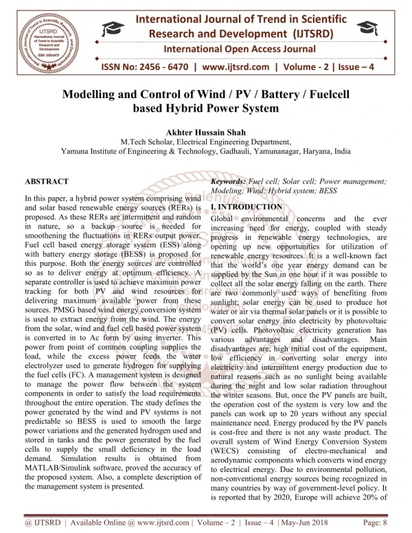
International Research Research and Development (IJTSRD) International Open Access Journal ontrol of Wind / PV / Battery / based Hybrid Power System International Journal of Trend in Scientific Scientific (IJTSRD) International Open Access Journal ISSN No: 2456 ISSN No: 2456 - 6470 | www.ijtsrd.com | Volume www.ijtsrd.com | Volume - 2 | Issue – 4 Modelling and Control of Wind based Fuelcell Akhter Hussain Shah M.Tech Scholar, Electrical Engineering Department Yamuna Institute of Engineering & Yamuna Institute of Engineering & Technology, Gadhauli, Yamunanagar, Haryana M.Tech Scholar, Electrical Engineering Department, Yamunanagar, Haryana, India Keywords: Fuel cell; Solar cell; Power management; Modeling; Wind; Hybrid system; BESS Modeling; Wind; Hybrid system; BESS Fuel cell; Solar cell; Power management; ABSTRACT In this paper, a hybrid power system comprising wind and solar based renewable energy sources (RERs) is proposed. As these RERs are intermittent and random in nature, so a backup source is needed for smoothening the fluctuations in RERs output power. Fuel cell based energy storage system (ESS) along with battery energy storage (BESS) is proposed for this purpose. Both the energy sources are controlled so as to deliver energy at optimum efficiency. A separate controller is used to achieve maximum power tracking for both PV and wind resources for delivering maximum available power from these sources. PMSG based wind energy conversion system is used to extract energy from the wind. The energy from the solar, wind and fuel cell based power system is converted in to Ac form by using inverter. This power from point of common coupling supplies the load, while the excess power feeds the water electrolyzer used to generate hydrogen for supplying the fuel cells (FC). A management system is designed to manage the power flow between the system components in order to satisfy the load requirements throughout the entire operation. The study defines the power generated by the wind and PV systems is not predictable so BESS is used to smooth the large power variations and the generated hydrogen used and stored in tanks and the power generated by the fuel cells to supply the small deficiency in the load demand. Simulation results is obtained from MATLAB/Simulink software, proved the accuracy of the proposed system. Also, a complete description of the management system is presented. In this paper, a hybrid power system comprising wind and solar based renewable energy sources (RERs) is proposed. As these RERs are intermittent and random in nature, so a backup source is needed for smoothening the fluctuations in RERs output power. cell based energy storage system (ESS) along with battery energy storage (BESS) is proposed for this purpose. Both the energy sources are controlled so as to deliver energy at optimum efficiency. A separate controller is used to achieve maximum power ing for both PV and wind resources for delivering maximum available power from these sources. PMSG based wind energy conversion system is used to extract energy from the wind. The energy from the solar, wind and fuel cell based power system to Ac form by using inverter. This power from point of common coupling supplies the load, while the excess power feeds the water electrolyzer used to generate hydrogen for supplying the fuel cells (FC). A management system is designed flow between the system components in order to satisfy the load requirements throughout the entire operation. The study defines the power generated by the wind and PV systems is not predictable so BESS is used to smooth the large enerated hydrogen used and stored in tanks and the power generated by the fuel cells to supply the small deficiency in the load demand. Simulation results is obtained from MATLAB/Simulink software, proved the accuracy of I. INTRODUCTION Global environmental concerns and the ever increasing need for energy, coupled with steady progress in renewable energy technologies, are opening up new opportunities for utilization of renewable energy resources. It is a well that the world’s one year energy demand can be supplied by the Sun in one hour if it was possible to collect all the solar energy falling on the earth. There are two commonly used ways of benefiting from sunlight; solar energy can be used to produce hot water or air via thermal solar panels or it is possible to convert solar energy into electricity by photovoltaic (PV) cells. Photovoltaic electricity generation has various advantages and disadvantages are; high initial cost of the equipment, low efficiency in converting solar energy into electricity and intermittent energy production due to natural reasons such as no sunlight being available during the night and low solar radiation throughout the winter seasons. But, once the PV panels are built, the operation cost of the system is very low and the panels can work up to 20 years without any special maintenance need. Energy produced by the PV panels is cost-free and there is not any waste product. The overall system of Wind Energy Conversion System (WECS) consisting of electro aerodynamic components which converts wind energy to electrical energy. Due to environmental pollution, non-conventional energy sources being recognized in many countries by way of government is reported that by 2020, Europe will achieve 20% of that by 2020, Europe will achieve 20% of Global environmental concerns and the ever increasing need for energy, coupled with steady progress in renewable energy technologies, are opening up new opportunities for utilization of renewable energy resources. It is a well-known fact ne year energy demand can be supplied by the Sun in one hour if it was possible to collect all the solar energy falling on the earth. There are two commonly used ways of benefiting from sunlight; solar energy can be used to produce hot rmal solar panels or it is possible to convert solar energy into electricity by photovoltaic (PV) cells. Photovoltaic electricity generation has various advantages and disadvantages are; high initial cost of the equipment, y in converting solar energy into electricity and intermittent energy production due to natural reasons such as no sunlight being available during the night and low solar radiation throughout the winter seasons. But, once the PV panels are built, tion cost of the system is very low and the panels can work up to 20 years without any special maintenance need. Energy produced by the PV panels free and there is not any waste product. The overall system of Wind Energy Conversion System nsisting of electro-mechanical and aerodynamic components which converts wind energy to electrical energy. Due to environmental pollution, conventional energy sources being recognized in many countries by way of government-level policy. It disadvantages. disadvantages. Main Main te description of @ IJTSRD | Available Online @ www.ijtsrd.com @ IJTSRD | Available Online @ www.ijtsrd.com | Volume – 2 | Issue – 4 | May-Jun Jun 2018 Page: 8
International Journal of Trend in Scientific Research and Development (IJTSRD) ISSN: 2456-6470 power consumed in there supplying by large-scale offshore wind farms. Besides, Europe is now planning for enlarging the capacity of the large-scale offshore wind farms to more than 50 GW power by 2018. Besides Europe, other countries such as China and USA also have promising offshore wind power resources and similar plans for wind farm installation. Alternate energy conversion systems such as PV panels and wind turbines can be combined with FC power plants to satisfy sustained load demands. An FC power plant uses hydrogen and oxygen to convert chemical energy into electrical energy. In this study, among the various types of FC systems, a Solid Oxide FC power plant is used because SOFC power plants have been found to be especially suitable for hybrid energy systems. In particular, advances in wind and PV energy technologies have increased their use in hybrid wind/PV/BESS configurations. Integrating PV and wind energy sources with fuel cells along with another storage device conventional metal hydride battery, leads to a non-polluting reliable energy source. The fuel cell generation system offers many advantages over other generation systems: low pollution, high efficiency, diversity of fuels, reusability of exhaust heat and on-site installation. by the customers and hence require mitigation techniques. The schematic of the standalone system using Wind/PV/Battery/Fuel cell based hybrid power system is shown in Fig. 1. Such a standalone wind energy system using PMSG is already being developed in [4]–[6]. In [4], the authors have not discussed the use of an energy storage device which is required to meet the power demand in the condition of low wind speed. Similarly, in [5] and [6], the authors are silent about the effect of unbalanced load which is a common phenomenon in the distribution network. Due to unbalanced load, the voltages at point of common coupling (PCC) become unbalanced. Moreover, unbalanced load will create pulsation in the generator torque which will reduce the life of the turbine shaft. In this paper, using battery and fuel cell along with aqua electrolyzer as the storage devices, a small-scale standalone power supply system based on wind energy is considered. Our objectives are: A.To achieve effective control coordination among the wind generator, PV system, battery and fuel cell to maintain the dc-link voltage constant. B.To maintain continuous supply at the ac bus (or load bus) as three phase dynamic loads need a balanced three-phase supply for their proper operation irrespective of variations in load, solar irradiance and wind speed. II. WIND/PV/BATTERY/FUELCELL BASED HYBRID POWER SYSTEM In many countries, there are remote communities where connection with the power grid is too expensive or impractical and diesel generators are often the source of electricity. Under such circumstances, a locally placed small-scale standalone distributed generation system can supply power to the customers. Autonomous wind power systems are among the most interesting and environment friendly technological solutions for the electrification of remote consumers. The control of an inverter to present the customers with a balanced supply voltage is the main challenge in a standalone system. Moreover, voltage variations, flickers, harmonic generation, and load unbalance are the major power quality (PQ) problems that occur in the wind energy conversion system (WECS). The voltage variations are mainly due to the change in load. Flicker or voltage fluctuations are primarily caused by variations in the power from WECS which comes into existence, owing to the fluctuations in the wind speed. Unwanted harmonics are generated due to the power electronics interface (rectifier, inverter and dc–dc converter) between the wind generator and the load. Those power quality problems may not be tolerated Fig. 1. Wind/PV/Battery/Fuel cell based hybrid power system A. Wind Energy Conversion System (WECS) In WECS, wind turbine provide mechanical power to PMSG for extracting energy from the wind and converting in to electrical energy. Two-mass driven system is modelled to couple wind turbine and PMSG. The wind turbine is subjected to variable wind speed which will be discussed in following @ IJTSRD | Available Online @ www.ijtsrd.com | Volume – 2 | Issue – 4 | May-Jun 2018 Page: 9
International Journal of Trend in Scientific Research and Development (IJTSRD) ISSN: 2456-6470 subsections. The WT has rated capacity of 8.5 kW. The PMSG also have same capacity as of WT. V IR V IR S S I I I exp 1 D PH 0 AV R (5) t SH B. PV Sytem The equivalent electrical circuit of a PV cell is given in Figure 2. It is a one diode model which is also known as the 5 parameter circuit. The cell can be modeled by other equivalent circuits as well; such as 7 parameters but the one diode model is the most commonly used circuit in the literature and the solution of the circuit is not as complicated as is the case in other models. The parameters in the circuit are; ID, IL, ISH, RSH, RS, I and V. Battery Energy Srorage System The battery energy storage system (BESS) comprises mainly of batteries, control and power conditioning system (C-PCS) and rest of plant. The rest of the plant is designed to provide good protection for batteries and C-PCS. The battery and C-PCS technologies are the major BESS components and each of these technologies is rapidly developing. Nickel Metal Hydride: each cell of a this battery comprises a positive electrode of lead dioxide and a negative electrode of sponge lead, separated by a micro-porous material and immersed in an aqueous sulfuric acid electrolyte. Discharge equation (i*>0) Q Q Exp ( s ) * * 1 f ( it , i , i ) E K . i K it Laplace 0 . 1 0 Q it Q it Sel ( s ) (6) Charge equation (i*<0) Fig. 2. Equivalent circuit of a solar cell From the circuit; Q Q Exp ( s ) * * 1 f ( it , i , i ) E K . i K it Laplace 0 . 2 0 it . 1 . 0 Q Q it Sel ( s ) (7) I I I I (1) PH D SH where, IPH (photo-generated current) is also called as IL (light current) which refers to direct current generated by photovoltaic effect. Whereas I is the output current of the cell. EBatt = Nonlinear voltage (V) E0 = Constant voltage (V) Exp(s) = Exponential zone dynamics (V) From Shockley’s diode equation; t nV Sel(s) = Represents the battery mode. Sel(s) = 0 during battery discharge, Sel(s) = 1 during battery charging. V IR S I I exp 1 D 0 (2) Where; K = Polarization constant (Ah−1) or Polarization resistance (Ohms) kT Vt q (3) i* = Low frequency current dynamics (A) By Ohm’s Law i = Battery current (A) V IR S I SH it = Extracted capacity (Ah) R (4) SH Q = Maximum battery capacity (Ah) After substituting equations (2), (3), and (4) into equation (1), the equation takes the form of; A = Exponential voltage (V) B = Exponential capacity (Ah)−1 @ IJTSRD | Available Online @ www.ijtsrd.com | Volume – 2 | Issue – 4 | May-Jun 2018 Page: 10
International Journal of Trend in Scientific Research and Development (IJTSRD) ISSN: 2456-6470 The parameters of the equivalent circuit can be modified to represent a particular battery type, based on its discharge characteristics. Consider a general reaction given as jJ + kK → mM where j moles of J and k moles of K react with each other to produce m moles of M. These reactants and products have an activity (a) associated with them. This activity is the ratio of the partial pressure of the gas and the standard pressure. Hence Gibbs free energy can be written as shown in the Equation (11) . ∆gf0 is the change in the Gibbs free energy of formation at standard pressure. Solid oxide fuel cell system The chemical energy of the fuel cell is defined by enthalpy of formation and Gibbs free energy. Gibbs free energy is the energy available to do external work which involves moving electrons around an external circuit. Enthalpy of formation is the sum of Gibbs free energy and the energy connected with entropy. In fuel cells, change in Gibbs free energy of formation (∆Gf) is considered, as this change is responsible for the energy released. j j k k a a . (11) 0 g g RT ln f f m M a III. Results and discussion The Wind/PV/Battery/FC hybrid power system individual components were modelled in detail in previous section using MATLAB Simulink. The system components have been grouped together to make the hybrid system. There are two cases are considered, these are: These quantities can be expressed in their ‘per mole’ form to make the comparisons easier. They are indicated by – over the lower case letter (gf ) which is given by Equation (8). (8) g g products g reactance f f f 1.Variable Solar Irradiance 2.Step load change For the hydrogen fuel cell, two electrons pass through the external circuit for each water molecule produced and each molecule of hydrogen used. In a lossless system, electrical work done is equal to the change in Gibbs free energy. Further, electrical work done to move a charge of 2F (to move two electrons) for a voltage of E is given by Equation (9). 1. Variable solar Irradiance For analyzing the validity of the HPS the system is subjected to different levels of solar irradiance. For the time interval 0-2 second the solar irradiance level is 1000 W/m2. From time interval between 2-6 second the solar irradiance level is reduced to 850W/m2 shown in the figure 5.1. As the irradiance level is decreased the output current and the output power of the PV system also decreased. For the simplicity only one time change in the solar irradiance is done otherwise the other waveforms will be overcrowded and cannot be clearly visible. Electrical work done = -2FE joules (9) Therefore E can be written as shown in Equation (10). This voltage is the open circuit voltage of the fuel cell. g (10) f E 2 F Fig. 3. .Solar Irradiance level @ IJTSRD | Available Online @ www.ijtsrd.com | Volume – 2 | Issue – 4 | May-Jun 2018 Page: 11
International Journal of Trend in Scientific Research and Development (IJTSRD) ISSN: 2456-6470 Fig. 4. .Solar Irradiance level Vs PV MPPT voltage Fig. 5. Output power of the different components of the HPS. As the output of the PV system reduces due to reduction in the irradiance level, it has to be compensated by the other components of the HPS, i.e. the main aim of this work. Fig 5. shows that when the PV output reduces. To overcome this BESS start giving power to the load. In the figure 5 shows the output power of the different components used in HPS. FC and BESS are the energy storage for a Stand- Alone Power System. BESs absorbs large fluctuations in RERs output and FC absorbs small fluctuations. Assembling PV panels, surface slope reduces the amount of this conversion and expected to increase the system performance and thus reduce the size of the equipment used. Adding a BESS plays an important role on the system performance and efficiency as well as the size of other components in the system. Increasing the number of batteries used also increases the system efficiency and decreases the other component sizes. On the other hand, the cost of the battery pack increases with a high rate while cost of other equipment decreases with a lesser rate. Conclusions The power management technique based upon classical PI controller is used for sharing the power according to the load and environmental conditions. The study shows how energy stored in the can be used as a key system performance indicator, provided that no system constraints are violated. The performance of the system can be significantly affected by the small variations made on the system elements. Auxiliary equipment brings extra load on the system but they are essential for steady and continuous operation of a stand-alone power system. If grid electricity is not used for auxiliary equipment, a battery pack or a fuel cell stack working continuously provide energy to these equipment. Since the control @ IJTSRD | Available Online @ www.ijtsrd.com | Volume – 2 | Issue – 4 | May-Jun 2018 Page: 12
International Journal of Trend in Scientific Research and Development (IJTSRD) ISSN: 2456-6470 6)M. E. Haque, M. Negnevitsky, and K. M. Muttaqi, “A novel control strategy for a variable-speed wind turbine with synchronous generator,” IEEE Trans. Ind. Appl., vol. 46, no. 1, pp. 331–339, Jan./Feb. 2010. panel continuously. and similar equipment should work a permanent-magnet References 1)S. Müller, M. Deicke, and W. De DonckerRik, “Doubly fed induction generator system for wind turbines,” IEEE Ind. Appl. Mag., vol. 8, no. 3, pp. 26–33, May/Jun. 2002. 7)N. Mohan, T. M. Undeland, and W. P. Robbins, Power Electronics: Converters, Applications, and Design. Hoboken, NJ: Wiley, 2002. 2)H. Polinder, F. F. A. van der Pijl, G. J. de Vilder, and P. J. Tavner, “Comparison of direct-drive and geared generator concepts for wind turbines,” IEEE Trans. Energy Convers., vol. 21, no. 3, pp. 725–733, Sep. 2006. 8)IEEE Guide for Optimizing the Performance and Life of Lead-Acid Batteries in Remote Hybrid Power Systems, IEEE Std. 1561-2007. 9)M. Whaley, W. L. Soong, and N. Ertugrul, “Investigation of switched-mode rectifier for control of small-scale wind turbines,” in Proc. IEEE Industry Applications Society Annual Meeting, 2005, pp. 2849–2856. 3)T. F. Chan and L. L. Lai, “Permanent-magnet machines for distributed generation: A review,” in Proc. 2007 IEEE Power Engineering Annual Meeting, pp. 1–6. 10)Muljadi, S. Drouilhet, R. Holz, and V. Gevorgian, “Analysis of permanent magnet generator for wind power battery charging,” in Proc. IEEE Industry Applications Society Annual Meeting, 1996, pp. 541–548. 4)M. Fatu, L. Tutelea, I. Boldea, and R. Teodorescu, “Novel motion sensorless control of stand alone permanent magnet (PMSG): Harmonics and negative sequence voltage compensation under nonlinear load,” in Proc. 2007 Eur. Conf. Power Electronics and Applications, Aalborg, Denmark, Sep. 2–5, 2007. synchronous generator 5)M. E. Haque, K. M. Muttaqi, and M. Negnevitsky, “Control of a stand alone variable speed wind turbine with a permanent magnet synchronous generator,” in Proc. IEEE Power and Energy Society General Meeting, Jul. 2008, pp. 20–24. @ IJTSRD | Available Online @ www.ijtsrd.com | Volume – 2 | Issue – 4 | May-Jun 2018 Page: 13