Download
1 / 4
40 likes | 55 Views
The light level in a room has a huge effect on one's mood and productivity. Lighting can contribute to your alertness and awakeness in the mornings, and it can either entice you to feel tired or keep you up all night. With all of these discoveries on the effects of lighting, it is becoming more and more important to be able to control lighting. In this paper, Bluetooth controlled AC dim light is constructed using TRIAC. The android application is developed using JDK in Android Eclipse which will control the on off function of the light bulb. Bluetooth wireless communication has been rising in popularity nowadays due to its low cost and wide range of applications. Moreover, most modern phones have Bluetooth, making it excellent controllers for Bluetooth supported devices. Serial data sent from the Android application is received by the Bluetooth receiver interfaced to the Arduino. Zero cross detection method is used for TRIAC gate trigger and Arduino uses serial data to generate appropriate pulses at a specific angle for TRIAC. Isolation between Arduino and ac source is considered and overall system is implemented using simulation and practical approaches. Zaw Min Min Htun | Kyaw Zin Latt | Myo Maung Maung "Development of Android Controlled AC Dim Light" Published in International Journal of Trend in Scientific Research and Development (ijtsrd), ISSN: 2456-6470, Volume-3 | Issue-5 , August 2019, URL: https://www.ijtsrd.com/papers/ijtsrd27965.pdf Paper URL: https://www.ijtsrd.com/engineering/electronics-and-communication-engineering/27965/development-of-android-controlled-ac-dim-light/zaw-min-min-htun<br>

E N D
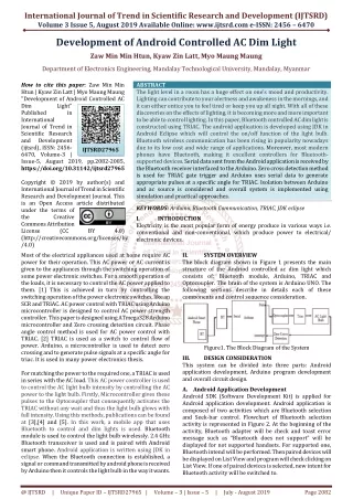
International Journal of Trend in Scientific Research and Development (IJTSRD) Volume 3 Issue 5, August 2019 Available Online: www.ijtsrd.com e-ISSN: 2456 – 6470 Development of Android Controlled AC Dim Light Zaw Min Min Htun, Kyaw Zin Latt, Myo Maung Maung Department of Electronics Engineering, Mandalay Technological University, Mandalay, Myanmar How to cite this paper: Zaw Min Min Htun | Kyaw Zin Latt | Myo Maung Maung "Development of Android Controlled AC Dim Light" Published in International Journal of Trend in Scientific Research and Development (ijtsrd), ISSN: 2456- 6470, Volume-3 | Issue-5, August 2019, pp.2082-2085, https://doi.org/10.31142/ijtsrd27965 Copyright © 2019 by author(s) and International Journal of Trend in Scientific Research and Development Journal. This is an Open Access article distributed under the terms of the Creative Commons Attribution License (CC (http://creativecommons.org/licenses/by /4.0) Most of the electrical appliances used at home require AC power for their operation. This AC power or AC current is given to the appliances through the switching operation of some power electronic switches. For a smooth operation of the loads, it is necessary to control the AC power applied to them. [1] This is achieved in turn by controlling the switching operation of the power electronic switches, like an SCR and TRIAC. AC power control with TRIAC using Arduino microcontroller is designed to control AC power strength controller. This paper is designed using ATmega328 Arduino microcontroller and Zero crossing detection circuit. Phase angle control method is used for AC power control with TRIAC. [2] TRIAC is used as a switch to control flow of power. Arduino, a microcontroller is used to detect zero crossing and to generate pulse signals at a specific angle for triac. It is used in many power electronics thesis. For matching the power to the required one, a TRIAC is used in series with the AC load. This AC power controller is used to control the AC light bulb intensity by controlling the AC power to the light bulb. Firstly, Microcontroller gives these pulses to the Optocoupler that consequently activates the TRIAC without any wait and thus the light bulb glows with full intensity. Using this methods, publications can be found at [3],[4] and [5]. In this work, a mobile app that uses Bluetooth to control and dim lights is used. Bluetooth module is used to control the light bulb wirelessly. 2.4 GHz Bluetooth transceiver is used and is paired with Android smart phone. Android application is written using JDK in eclipse. When the Bluetooth connection is established, a signal or command transmitted by android phone is received by Arduino then it controls the light bulb in the way it wants. ABSTRACT The light level in a room has a huge effect onone’s mood and productivity. Lighting can contribute to your alertness and awakeness in the mornings, and it can either entice you to feel tired or keep you up all night. With all of these discoveries on the effects of lighting, it is becoming more and more important to be able to control lighting. In this paper, Bluetooth controlled AC dim light is constructed using TRIAC. The android application is developed using JDK in Android Eclipse which will control the on/off function of the light bulb. Bluetooth wireless communication has been rising in popularity nowadays due to its low cost and wide range of applications. Moreover, most modern phones have Bluetooth, making it excellent controllers for Bluetooth- supported devices. Serial data sent from the Android application is received by the Bluetooth receiver interfaced to the Arduino. Zero cross detection method is used for TRIAC gate trigger and Arduino uses serial data to generate appropriate pulses at a specific angle for TRIAC. Isolation between Arduino and ac source is considered and overall system is implemented using simulation and practical approaches. KEYWORDS: Arduino, Bluetooth Communication, TRIAC, JDK eclipse I. INTRODUCTION Electricity is the most popular form of energy produce in various ways i.e. conventional and non-conventional, which produce power to electrical/ electronic devices. IJTSRD27965 BY 4.0) II. The block diagram shown in Figure 1 presents the main structure of the Andriod controlled ac dim light which consists of: Bluetooth module, Arduino, TRIAC and Optocoupler. The brain of the system is Arduino UNO. The following sections describe in details each of these components and control sequence consideration. SYSTEM OVERVIEW Figure1. The Block Diagram of the System III. This system can be divided into three parts: Android application development, Arduino program development and overall circuit design. A.Android Application Development Android SDK (Software Development Kit) is applied for Android application development. Android application is composed of two activities which are Bluetooth selection and Seek-bar control. Flowchart of Bluetooth selection activity is represented in Figure 2. At the beginning of the activity, Bluetooth adapter will be check and toast error message such as “Bluetooth does not support” will be displayed for not supported handsets. For supported one, Bluetooth intend will be performed. Then paired devices will be displayed on List View and program will check clicking on List View. If one of paired devices is selected, new intent for Bluetooth activity will be switched to. DESIGN CONSIDERATION @ IJTSRD | Unique Paper ID – IJTSRD27965 | Volume – 3 | Issue – 5 | July - August 2019 Page 2082
International Journal of Trend in Scientific Research and Development (IJTSRD) @ www.ijtsrd.com eISSN: 2456-6470 In Bluetooth activity, default HC-06 UUID “00001101-0000- 1000-8000-00805F9B34FB" is applied. Android Seek-Bar UI (user interface) is mainly applied for desire light intensity control. Seek-bar has so many Listeners or methods to be applied. Among them set On Seek Bar Changed Listener method is applied. In this method, three sub-event included which are on Stop Tracking Touch, on Start Tracking Touch and on Progress Changed events. The on Progress Changed listener will catch every movement of Seek-Bar and Bluetooth communication can be delayed. So on Stop Tracking Touch method is applied for Seek-Bar control as shown in Figure 3. As soon as the touch on Seek-Bar stop, Seek-Bar value will be collect and added “x” character and “\r\n” “carriage return” and “line feed” characters for character encryption for Arduino program decryption. B.Arduino Program Development The Arduino (IDE) integrated development environment is a cross-platform application (for Windows, macOS, Linux) that is written in the programming language Java. The Arduino IDE supplies a software library from the wiring project, which provides many common input and output procedures. Figure 4 shows the flowchart of Arduino program. Figure 2 Flowchart for Bluetooth activity Figure4. Flowchart of Arduino Program In this section, 9600 baud rate serial UART communication is applied. Every valid character is matched and String Str collected digits 48 ASCII number to 57 ASCII ranges. As soon as ‘x’ character is detected the string Str is converted into T value. Then T value is align to the positive half cycle of ac wave or 0 to 180 degree variation or 0 to 10 millisecond interval. Whenever interrupt signal is detected, time delay will start and pulse generation will occur after delay time in finished. C.Overall Circuit Design HC-06 module is applied and it is an easy to use Bluetooth SPP (Serial Port Protocol) module, designed for transparent wireless serial connection setup. As shown in Figure 5, Serial port Bluetooth module is fully qualified Bluetooth V2.0+EDR Figure 3 Flowcharts for Seek-Bar Activity @ IJTSRD | Unique Paper ID – IJTSRD27965 | Volume – 3 | Issue – 5 | July - August 2019 Page 2083
International Journal of Trend in Scientific Research and Development (IJTSRD) @ www.ijtsrd.com eISSN: 2456-6470 (Enhanced Data Rate) 3Mbps Modulation with complete 2.4GHz radio transceiver and baseband. In this work, as shown in Figure 6, MOC3023 is chosen to detect zero-cross signal. MOC3023 is a non-Zero-Cross Voltage opto-isolator TRIAC driver. It is a via hole arbitrary phase TRIAC driver output Optocoupler in 6 pin DIP package. AC loads can be used not only ON/OFF control but also phase control. In this paper, the original frequency (50Hz) will not be changed and the dim light will be control according to the firing angle. The supply voltage is 220Vrms and it has Vmax = Squrt(2)*220V or 315V high. That voltage is rectified using bridge and reduced to 3V range for LED using voltage sharing 47kΩ 5W resistor. When this AC voltage across the zero level line, the Infrared LED of optocoupler will be off and phototransistor will be off too. At that time, the output of zero cross sensing circuit will be high. When AC voltage is not zero, LED of optocoupler will be on and phototransistor will be on and it makes short circuit to output. Every ten millisecond, zero cross signal will be HIGH for normal 50 Hz AC voltage. Figure5. HC06 Bluetooth Module This system includes a GaAs infrared emitting diode and a light activated acoustic switch that acts like a TRIAC. Common applications include solenoid/valve management, traffic lighting, stationary AC power change, vending machines, incandescent lamp dimmers, solid-state relays and lamp ballasts. industrial controls, Figure8. Overall Circuit Diagram of the System Zero cross signal is sensed by interrupt pin or pin 2 of Arduino and pin 3 is used for TRIAC driver. MOC3023 TRIAC based optocoupler is applied for AC voltage firing. A4 and A5 pins are used for I2C LCD and Rx pin or pin 0 is attached to Tx pin of HC-06 Bluetooth module. The above Figure 8 shows the overall circuit diagram of the system. IV. TESTS AND RESULTS Firstly, simulation test is performed using Proteus VSM. The following figure 9 shows the response of Bluetooth serial data using Proteus simulation and Arduino Serial monitor. For this test, USB to serial converter module is applied with Bluetooth module. The name, password and baudrate of Bluetooth can be change by connection like this. Using Virtual Terminal tool, signal from Bluetooth can be seen clearly in Proteus software. Figure6. MOC3023 Optocoupler In this system, BTA16-600 TRIAC shown in Figure 7, is used to control the 220V AC light bulb. TRIAC, from triode for alternating current, is a generic trademark for a three terminal electronic component that conducts current in either direction when triggered. It is a glass passivized TRIAC in a plastic envelope, intended for use in application requiring high bidirectional transient and blocking voltage capability and high thermal cycling performance. Typical application of BTA16 600 TRIAC are motor control, industrial and domestic lighting, heating and static switching. Figure9. Simulation Test using Proteus and Arduino Serial Monitor for Bluetooth Signal Zero cross detection circuit and TRIAC driver circuit are tested using Proteus as shown in Figure 10. For I2C (Inter- Integrated Communication) LCD, PCF8574 I2C module is applied for simulation. Figure7. BTA16-600AC loads can be used not only @ IJTSRD | Unique Paper ID – IJTSRD27965 | Volume – 3 | Issue – 5 | July - August 2019 Page 2084
International Journal of Trend in Scientific Research and Development (IJTSRD) @ www.ijtsrd.com eISSN: 2456-6470 For faster circuit response, potentiometer based direct firing test is performed there. The simulation result of test in Figure 10 can be seen in Figure 11. Using Bluetooth connection, experimental test is performed as shown in Figure 17. So, the light can be controlled by using the android apk. It can become one of the needed parts of the daily environment. The pink wave represents the response of zero cross detection circuit and the green wave represents the trigger pulse for TRIAC driver circuit. The delay time between zero cross signal and TRIAC pulse can be adjusted using Potentiometer. But in experimental test, Bluetooth signal is applied instead of using Potentiometer. (a) Figure 10 Simulating overall circuits (b) (c) Figure 14 Experimental Result of (a) 0% and 10% firing angle (b) 20% and 30% firing angle (c) 40% and 50% firing angle Figure 11 Simulation result of overall circuit V. In this paper the design and implementation of a control system for Android based dim light has been established. This system consists of Android and Arduino based programming and electronic circuit design. Not only for light bulb, but also for ac motor it can be applied too. Except Bluetooth, WI-Fi or Serial communication can be applied as further extension. Stable lighting output is produced by means of electronic circuit design and programming development. REFERENCES [1]Prachi M. Palpankar, SanrajHarle, TusharKarade, SurajLekurwaledbacer Nagpur, “Speed control of induction motor using TRIAC”, Proceedings of 18th IRF International Conference, 11th January 2015, Pune, India, [2]A. C. Krishna, K. Karthik, S. Sidharth, Project Report on “Speed Control of single phase induction motor By using TRIAC”, of GRI of Engineering Heydrabad.2012. [3]Koji Namihana, Masayoshi Sato: “New control method of three-phase induction motor”, RENGA No.159, pp.23-28 (1999). [4]Power Electronics by M D SINGH and K B KHANCHANDANI Tata McGraw Hill Publishing Company, 1998. [5]Sandeepkumar, Pritamsatsangi “TRIAC based closed loop control of Induction motor,” IEEE Trans. Ind, 1989. CONCLUSIONS AND DISCUSSION Figure 12 Simulating using Android Virtual Device For controlling delay time, Seek-Bar progress is setup 0 to 1023 and this value is converted into 8000 µS to 300 µS delay time. Theoretically that interval should be 10000 µS to 0 µS delay. For avoiding leakage, 8000 µS to 300 µS interval is safe to be applied practically. Figure 13 Experimental Setup of the Whole System Figure 13.shows experimental setup for circuit construction of AC dim light. A small transformer and rectifier with capacitor is used for powering Arduino. @ IJTSRD | Unique Paper ID – IJTSRD27965 | Volume – 3 | Issue – 5 | July - August 2019 Page 2085