Download
1 / 4
40 likes | 53 Views
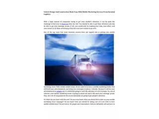
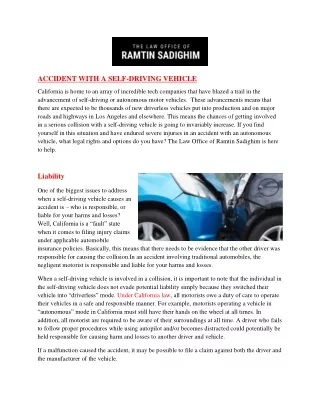
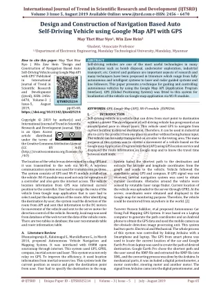
Self driving vehicles are one of the most useful technologies in many applications such as bomb disposal, underwater exploration, industrial transport etc. Control and guidance are important aspects of research and many techniques have been proposed in literature which range from fully autonomous and intelligent systems to laser and radar guided systems and line followers. This paper presents a technique for guiding and controlling autonomous vehicles by using the Google Map API Application Program Interface . GPS Global Positioning System was fitted to this system for localization of the vehicle on Google map application via Wi Fi module. May Thet Htar Nyo | Win Zaw Hein "Design and Construction of Navigation Based Auto Self-Driving Vehicle using Google Map API with GPS" Published in International Journal of Trend in Scientific Research and Development (ijtsrd), ISSN: 2456-6470, Volume-3 | Issue-5 , August 2019, URL: https://www.ijtsrd.com/papers/ijtsrd25214.pdf Paper URL: https://www.ijtsrd.com/engineering/electronics-and-communication-engineering/25214/design-and-construction-of-navigation-based-auto-self-driving-vehicle-using-google-map-api-with-gps/may-thet-htar-nyo<br>

E N D
International Journal of Trend in Scientific Research and Development (IJTSRD) Volume 3 Issue 5, August 2019 Available Online: www.ijtsrd.com e-ISSN: 2456 – 6470 Design and Construction of Navigation Based Auto Self-Driving Vehicle using Google Map API with GPS May Thet Htar Nyo1, Win Zaw Hein2 1Student, 2Associate Professor 1,2Department of Electronic Engineering, Mandalay Technological University, Mandalay, Myanmar How to cite this paper: May Thet Htar Nyo | Win Zaw Hein "Design and Construction of Navigation Based Auto Self-Driving Vehicle using Google Map API with GPS" Published in International Journal of Trend in Scientific Research and Development (ijtsrd), ISSN: 2456- 6470, Volume-3 | Issue-5, August 2019, https://doi.org/10.31142/ijtsrd25214 Copyright © 2019 by author(s) and International Journal of Trend in Scientific Research and Development Journal. This is an Open Access article distributed under the terms of the Creative Commons Attribution License (CC BY (http://creativecommons.org/licenses/by /4.0) The location of the vehicle was determined by using GPS and it was transmitted to the web via Wi-Fi. A wireless communication system was used for transmission purpose. The system consists of GPS and Wi-Fi module installed on the vehicle. Wi-Fi module was used not only for operation as a controller and also gets the internet access. The vehicle location information from GPS was informed current position to the controller. User had to assign the route of the vehicle from Google map application that is user had to select and put the designation of the route. After identifying the destination by user, the system read the direction of the route from API and sent that information to the DC motors for movement of the vehicle and sent to the servo motor for direction control of the vehicle. Recently, local map was used from database of the web to test the data of the vehicle route. There are two tables in database; the user recommends table and route information table. A.Literature Review Dhanasingaraja R., Kalaimagal S., Muralidharan G., in March 2014, proposed Autonomous Vehicle Navigation and Mapping System. It was interfaced with OSRM open sourcemap through internet. This system used GPS, GPRS, compass, inertial sensor and laser. This system was not only relay on GPS. To improve the efficiency, it used location information from inertial sensors too. This system took the current position as source and gets the destination point from user. User had to specify the destination in the map. ABSTRACT Self-driving vehicles are one of the most useful technologies in many applications such as bomb disposal, underwater exploration, industrial transport; etc. Control and guidance are important aspects of research and many techniques have been proposed in literature which range from fully autonomous and intelligent systems to laser and radar guided systems and line followers. This paper presents a technique for guiding and controlling autonomous vehicles by using the Google Map API (Application Program Interface). GPS (Global Positioning System) was fitted to this system for localization of the vehicle on Google map application via Wi-Fi module. KEYWORDS: GPS, Google Map (API), Wi-Fi module (ESP8266. I. INTRODUCTION Self-driving vehicle is a vehicle that can drive from start point to destination without a driver. The development of self-driving vehicle has progressed at an unanticipated pace in recent years. This vehicle used GPS to navigate from current location to desired destination. Therefore, it can be used in industrial site to carry the product from one place to another without being human input. The vehicle can be easily transported on a trailer to the testing area. The main purpose of this system was to control a movement of a vehicle based on the Google map Application Program Interface (API) using GPS location service and displayed the route information on Google map and to know the travel time between each node. System found the shortest path to the destination and extracts the latitude and longitude coordinates from the graph and sends to the vehicle. Vehicle followed the coordinate using GPS and compass. If GPS signal was not received, inertial navigation system was used to obtain current coordinate. Obstacles around the vehicle were sensed by rotatable laser range finder. Current location of the vehicle was uploaded to the server through GPRS. At the server, coordinates were obtained and displayed in the Google map for monitoring purpose. Therefore, the vehicle could be monitored from anywhere in the world. [2] Tanveer Hossen Sakkhor, et.al proposed Autonomous Car Using Full Mapping GPS System. It was based on a Laptop computer to generate the path coordinates and an Android phone to obtain the GPS data and used the mobile camera as the obstacle detection image processing unit. This system had two parts: Electrical and Mechanical. The whole process of this system was controlled by linking Arduino with a Smartphone and laptop. The GPS from smart phone was used to locate the current location of the car and Google Earth Pro from laptop was used to create the path of desired destination. Google Earth Pro chose the shortest path and the user saved the KMP file and extracted the KMP file into XML, and the converting process was done by the Arduino. In mechanical parts, it was included a digital potentiometer, a motor controller, steering motor and another motor. The signal from Arduino came into the digital potentiometer, and IJTSRD25214 pp.65-68, 4.0) @ IJTSRD | Unique Paper ID – IJTSRD25214 | Volume – 3 | Issue – 5 | July - August 2019 Page 65
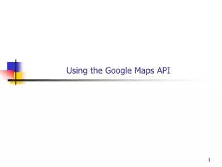
International Journal of Trend in Scientific Research and Development (IJTSRD) @ www.ijtsrd.com eISSN: 2456-6470 it controlled the voltage to change the speed of the car. The digital potentiometer sent required instructions to the motor controller. Motor controller controlled the whole process of the motor of the car as rpm, turning, speed etc. Another motor controller was used for the steering movement. This motor controller controlled the steering movement and it’s directly linked with the Arduino. Gyro sensor was used for the direction purpose. It worked as a compass to control the desired direction of vehicle. Other sensor included IR sensor and Sonar sensor for obstacle detection [1]. B.Appliances of Web Technology Web is the most critical technology to carry data via internet. The primary function of a web server is to store, process and deliver web pages to clients. Generally, most of the web servers support server-side scripting using Active Server Pages (ASP), PHP or other scripting languages. Web servers are not only used for serving the World Wide Web but also found embedded in devices such as printers, routers, and webcam. No additional software has to be installed on the client computer because only a web browser is required. There are three main parts in this technology. They are hypertext document, web server and web browser. The communication between client and server takes place using the Hypertext Transfer Protocol (HTTP). Pages delivered are most frequently Hypertext Mark-up Language (HTML) documents, which may include images, style sheets and scripts in addition to text content. Hypertext document also called web document is a text document including HTML element. The basic function of web browser is to carry the data from user to web server and vice versa. The most popular web browsers are Microsoft Internet Explorer, Mozilla Firefox, Google Chrome, Apple Safari and Opera. II. SYSTEM BLOCK DIAGRAM Basically, the proposed system was included DC motor for vehicle movement, servo motor for lane control, Node MCU for control program, GPS for localization, user guidance map for direction finding as shown in figure 1. The flow chart of main control program was shown in figure 2. In this flowchart, the system was initialized firstly. And then loading the map and localize the current position. After the user was identified the destination, the vehicle is started to drive. The path from start to destination is actually a set of coordinates that form a line. These coordinates could be considered nodes. The vehicle can reach its destination by going again and again through each node, eventually leading to the destination. Figure2 Overall System Flow Chart III. There were two main parts in this system: direction finding using user instruction (guided map/ local map) and apply route (such as degree angle) control to the vehicle driving. In direction finding process, paths were calculated in control program that included in ESP8266 Wi-Fi module. A route planner offered directions from one specific location to another. There was an angle between two coordinates called vehicle’s heading. The vehicle heading also had to be calculated in this case to justify the direction. The goal of the vehicle was to try and maintain the heading between the current position and the next node. Each node could be considered a current goal. By reaching the current goal, the next node became the goal, therefore recursively the vehicle iterated again through each current goal to the final goal. The controller drives the DC motor by L298N motor driver for continuous movement. There are three methods in controlling the speed of DC motor: Flux Control, Armature Voltage Control, and Supply Voltage Control (PWM). Both flux control and armature voltage control cannot provide speed control in the desirable range. Whereas the armature voltage control method involves huge power loss due to its usage of resistors in series with the armature. Therefore, Pulse Width Modulation (PWM) method was used to control the DC motor. Pulse Width Modulation (PWM) is a method for binary signals generation. It has two signal periods (high and low). The width (W) of each pulse varies between 0 and the period (T) as shown in figure 3. The main principle is control of power by varying the duty cycle. METHODOLOGY Figure1 Overall System Block Diagram This system was based on web technology, GPS technology and Application Program Interface (API). The functional block diagram is shown in figure 1. In this figure, GPS supported only current position of vehicle as longitude and latitude. Google map was used to assign the map from start point to destination. The direction of vehicle was measured by servo motor to follow the direction of navigation. The control program was installed in Node MCU: ESP8266 module. This module supports Wi-Fi access for web development. Motor driver L298N was used to control the movement of vehicle and the magnetometer was used to justify the heading of the vehicle. Figure 3 Pulse Width Modulation (PWM) of DC motor @ IJTSRD | Unique Paper ID – IJTSRD25214 | Volume – 3 | Issue – 5 | July - August 2019 Page 66
International Journal of Trend in Scientific Research and Development (IJTSRD) @ www.ijtsrd.com eISSN: 2456-6470 In this figure, where T=Ton+Toff, T=time period, Ton=ON time and Toff=OFF time. Distance between a pair of latitude and longitude was calculated using Haversine formula because it provides greater accuracy. Haversine formula gives the shortest distance over the surface of the earth. It is shown as follows; Distance=R c In this figure, DC motor was set up on rare wheels and servo motor was fitted up on front wheels. L298N motor driver was used for DC motor driving. 5V, 3A voltage regulator was used for stable power supply and it was desired to protect battery power un-stabilization. Sometime, battery power is in constant and the current of battery would be down when battery has been using for long time. Figure 5 shows measurement plans for angle accuracy of servo motor driving unit of the vehicle. In this plans, example measurement of angle driving was shown in figure 6. According to this figure, the degrees were measured as 30, 60, 90, and 120 degree respectively. (1) (2) (3) Where, R=radius of earth, 6371km, = difference in latitude (lat2-lat1), = difference in longitude (lon2-lon1), = the angular distance, = the square of half the chord length between the points. IV. EXPERIMENTALSETUP There were hardware and software parts in this system. In hardware part, GPS module (Neo 7N), Wi-Fi module (ESP8266), Motor Driver (L298N), and CA 1253 voltage conversion module were installed on the car kit. In GPS module, Rx and Tx were connected to microcontroller digital pins 3 and 4. In this system, Wi-Fi module operated as a microcontroller and it was also used to get the internet access. In Wi-Fi module, digital pins 9 and 10 operated as Rx and Tx. GPS receiver was required to get the current location of the vehicle. Once the Wi-Fi module and GPS module have assembled, the GPS module was almost ready to get the location information of the vehicles. In software part, Arduino IDE, xampp, HTML, Java script, PHP languages were used to complete the system. In this work, there were two parts of the whole system; vehicle part and direction control part. The movement and direction control were examined by Arduino Uno and the desired route control were examined by Google map API. The movement of desired vehicle was controlled by DC motor driver and the direction angle of vehicle heading was controlled by servo motor. The control program was developed by Arduino IDE and it was installed in Arduino UNO. The movement accuracy was measured and analyzed practically. Figure 4 shows complete hardware design representation of the system. Figure5 – Preparing to Measure the Turning Angle Figure 6 shows comparison of setting time in control process and angle degree movement of the vehicle. In this figure, the first column was shown PWM value and it was 200 for all angle control, the second column was represented as time in millisecond and the third column was angle degree movement. Before practical test for servo motor control, the PWM waveform was simulated in proteus software as shown in figure 7 and 8. Figure6 Measuring Turning Angle In the figure 7, the PWM is for 90 degree movement of servo motor and in the figure 8, 145 degree movement of servo motor. From these two figures; the PWM is wider for larger degree control of vehicle. Figure.4 Complete Hardware Design of Vehicle Figure7 Example representing of 90° Pulse Width of Servo @ IJTSRD | Unique Paper ID – IJTSRD25214 | Volume – 3 | Issue – 5 | July - August 2019 Page 67
International Journal of Trend in Scientific Research and Development (IJTSRD) @ www.ijtsrd.com eISSN: 2456-6470 to destination. In each node; distance (meter), acceleration, current latitude and longitude were measured and represented and then, next node latitude and longitude, heading information and address from node to node were also included. From that information, the vehicle was controlled to move according to this direction from the start point to the destination as shown in figure 12. Figure8 Example representing of 145° Pulse Width of Servo The location of the vehicle was uploaded in web application such as Google map. The data uploading to the web server was shown in figure 9. In this case, the free web application was used in this system. Figure12. Route showing on Google map Figure 12 shows the route on Google map. In figure, the first part was represented as latitude and longitude value of current location and then, the next line was the latitude and longitude value of the destination that was assigned by user. The blue line was the desired route of the vehicle. From this, the vehicle was driven by Google map API easily and the current location of the vehicle was shown as a blink point using GPS navigation. V. CONCLUSION This system depending on the web application, the whole information of the vehicle is stored to the server. The accuracy of the system depends on the internet speed of the Wi-Fi network. In this system, the major problem was the accuracy of DC motor in this vehicle kit because the efficiency of each motor which is available in commercial market is not same. Sometime, the left motor is faster than the right motor even in one kit set. Therefore, the vehicle cannot drive straight forward with the same PWM value. This vehicle can go only 12 inches in 857ms. The maximum turning angle of servo must be different in another car kit. In this vehicle, servo motor can turn 0° to 145°. This research tends to drive, without human supervision, within limited and carefully mapped area and to be used more easily in the industrial area. This system can reduce risky and dangerous driver behavior. Acknowledgment Author thanks to Dr.Win Zaw Hein, Associate Professor, Department of Electronic and Communication Engineering for kind permission to prepare for this paper, for his close supervision, helpful advice, encouragement and numerous invaluable guidance. The author would also thank to all teachers and friends who willingly helped the author throughout the preparation of the paper. REFERENCE [1]Tanveer Hossen Sakkhor 12121181Samin Saksiat Zaman-11221003 Md. Arafat Al Sadi-11121098 Abdullah Al Nayeem Mahmud-11121049, “Autonomous Car Using Full Mapping GPS System” [2]Dhanasingaraja R, Kalaimagal S, Muralidharan G “Autonomous Vehicle Navigation and Mapping System” March 2014 [3]Arvind “Optimizing the turning radius of a vehicle using symmetric four wheel steering system” December-2013 [4]Onishim Hasdak (09201003) , “Programming a Self- Driving Car” August 2015 Figure9 Creation of data uploading in free web application When data was successfully uploaded in the web, it was shown as “A record has been inserted” as shown in figure 10. Create free web and file is uploaded to get the location and to map the vehicle current position. Figure10 Notification of Upload Data Done The direction control part of the vehicle was completed by Google map API and current location of the vehicle was supported by GPS. The figure 11 shows the example direction control of the vehicle. (A) (B) Figure11 Example route information show on serial monitor Figure 11 shows the example route information that was assembled in serial monitor. In the figure 11 (B), there were five nodes to assign for one complete route from start point @ IJTSRD | Unique Paper ID – IJTSRD25214 | Volume – 3 | Issue – 5 | July - August 2019 Page 68