Download
1 / 11
110 likes | 182 Views
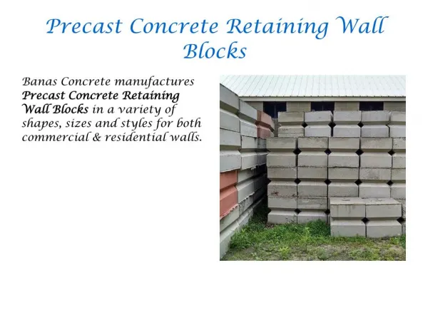
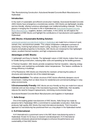
India is one of the highly populated countries of the world. It ranks the second in population next to China. Besides, major section of the people live below poverty line. Due to over population, poverty, high land value and house deficit, major cities like Delhi and Mumbai are covered by slums. These slums not only make our country aesthetically bad but also the people living in such slums are deprived from basic facilities like proper sanitation, health care, and proper housing. The provision of affordable housing for these poor people needs to be facilitated by certain provisions. This can be possible only by introducing such technologies and materials that can be beneficial for building low cost houses. Researchers worldwide have made significant efforts to find sustainable and affordable technologies to arrest the situation. Appropriate solution for affordable housing will vary from one location to another. Some general rules, however, apply to construction methods and housing systems. This project aims for developing a technology called dry stacking or mortar less buildings made from interlocking blocks. Mortarless brick construction, usually employing interlocking bricks, is growing in popularity round the world, indicative of acceptability. Mortarless techniques demonstrate the following advantages increase of construction productivity, reduction in construction duration and labor and reduced construction cost. Because of its technological simplicity and local resource dependence, mortarless block construction is more appropriate to many local communities than conventional mortared brick techniques. Mohammad Vekas Wani | Mr. Chitranjan Kumar "Behaviour of Interlocking Hollow Concrete Blocks" Published in International Journal of Trend in Scientific Research and Development (ijtsrd), ISSN: 2456-6470, Volume-2 | Issue-5 , August 2018, URL: https://www.ijtsrd.com/papers/ijtsrd18203.pdf Paper URL: http://www.ijtsrd.com/engineering/civil-engineering/18203/behaviour-of-interlocking-hollow-concrete-blocks/mohammad-vekas-wani<br>

E N D
International Research Research and Development (IJTSRD) International Open Access Journal Behaviour of Interlocking Hollow Concrete Blocks Behaviour of Interlocking Hollow Concrete Blocks International Journal of Trend in Scientific Scientific (IJTSRD) International Open Access Journal ISSN No: 2456 ISSN No: 2456 - 6470 | www.ijtsrd.com | Volume 6470 | www.ijtsrd.com | Volume - 2 | Issue – 5 Behaviour of Interlocking Hollow Concrete Blocks Mohammad Vekas Wani Mohammad Vekas Wani1, Mr. Chitranjan Kumar2 1Student, 2Assistant Professor Department of Civil Engineering, Al-Falah School of Engineering and Technology Falah University, Dhauj, Faridabad, Haryana, India Department of Civil Engineering, Al Al-Falah University, Dhauj, Faridabad, Haryana, India Engineering and Technology ABSTRACT India is one of the highly populated countries of the world. It ranks the second in population n Be sides, major section of the people live below poverty line. Due to over population, poverty, high land value & house deficit, major cities like Delhi & Mumbai are covered by slums. These slums not only make our country aesthetically bad but also the people living in such slums are deprived from basic facilities like proper sanitation, health care, and proper housing. The provision of affordable housing for these poor people needs to be facilitated by certain provisions. This can be possible only by introducing such technologies and materials that can be beneficial for building low-cost houses. Researchers worldwide have made significant efforts to find sustainable and affordable technologies to arrest the situation. Appropriate solution for affordable housing will vary from one location to another. Some general rules, however, apply to construction methods and housing systems. This project aims for developing a technology called dry stacking or mortar less buildings made from interlocking blocks. Mortar less brick construction, usually employing interlocking bricks, is growing in popularity round the acceptability. Mortarless techniques demonstrate the following advantages: increase of construction productivity, reduction in construction duration and lab or and reduced construction cost. Because of its technological simplicity dependence, mortar less-block construction is more appropriate to many local communities than conventional mortared-brick techniques. INTRODUCTION Masonry construction of structures offers many advantages over traditional wood framing, including increased strength, fire resistance and insulation value. Traditionally, masonry construction techniques involved taking masonry manufactured cement, sand, water & aggregate, “buttering” the units with mortar, typically mixed from cement, sand water and lime, buttered units to form a number of courses. However, this technique has a number of disadvantages. First, the weakest part of such a masonry wall is the mortar joint, as the substitution of lime for aggregate reduces the overall strength of the joint. Second, the need to butter and precisely fit each block necessitates the use of skilled, and typically highly paid, masons. Finally, the mortar used to butter the units often hardens on the inside of openings within the blocks, preventing or hindering the insertion reinforcements within the openings. One solution to the lack of strength of mortar joints has been to dry stack the masonry units. In a typical dry stacked wall, the masonry units are stacked in a staggered arrangement and are reinforced by inserting steel rebar through interlocking holes. Once reinforced, a skin made up of fibreglass and a cementicious material may be applied to the front and back faces of the walls to provide additional reinforcement. Adding the skin to the front and back faces of the wall increases the stability of the wall by up to ten times the stability of a wall without such a skin and provides an additional barrier to prevent cold and warm air from passing through the joints between masonry units. Therefore, the use of such a skin is preferred in these types of walls. However, dry stacking of walls is not without drawbacks. First, like the staking of mortar walls, care must be taken to ensure that the mortar walls, care must be taken to ensure that the India is one of the highly populated countries of the world. It ranks the second in population next to China. section of the people live below poverty line. Due to over population, poverty, high land value & house deficit, major cities like Delhi & Mumbai are covered by slums. These slums not only make our country aesthetically bad but also the people living in such slums are deprived from basic facilities like proper sanitation, health care, and proper housing. Masonry construction of structures offers many advantages over traditional wood framing, including ire resistance and insulation value. Traditionally, masonry construction techniques involved taking masonry manufactured cement, sand, water & aggregate, “buttering” the units with mortar, typically mixed from cement, sand water and lime, and stacking the buttered units to form a number of courses. However, this technique has a number of disadvantages. First, the weakest part of such a masonry wall is the mortar joint, as the substitution of lime for aggregate reduces f the joint. Second, the need to butter and precisely fit each block necessitates the use of skilled, and typically highly paid, masons. Finally, the mortar used to butter the units often hardens on the inside of openings within the blocks, preventing or indering the insertion reinforcements within the openings. One solution to the lack of strength of mortar joints has been to dry stack the masonry units. In a typical dry stacked wall, the masonry units are stacked in a staggered gement and are reinforced by inserting steel rebar through interlocking holes. Once reinforced, a skin made up of fibreglass and a cementicious material may be applied to the front and back faces of the walls to provide additional reinforcement. Adding skin to the front and back faces of the wall increases the stability of the wall by up to ten times the stability of a wall without such a skin and provides an additional barrier to prevent cold and warm air from passing through the joints between masonry units. Therefore, the use of such a skin is preferred in these types of walls. However, dry stacking of walls is not without drawbacks. First, like the staking of units, units, typically typically for these poor people needs to be facilitated by certain provisions. This can be possible only by introducing such technologies and materials that can be beneficial for cost houses. Researchers worldwide ustainable and affordable technologies to arrest the situation. Appropriate solution for affordable housing will vary from one location to another. Some general rules, however, apply to construction methods and housing of of insulation insulation and/or and/or This project aims for developing a technology called dry stacking or mortar less buildings made from brick construction, usually employing interlocking bricks, is growing in popularity round the bility. Mortarless techniques demonstrate the following advantages: increase of construction productivity, reduction in construction duration and or and reduced construction cost. Because of its technological simplicity block construction is more appropriate to many local communities than brick techniques. world, world, indicative indicative of of and and local local resource resource @ IJTSRD | Available Online @ www @ IJTSRD | Available Online @ www.ijtsrd.com | Volume – 2 | Issue – 5 | Jul-Aug 2018 Aug 2018 Page: 1853
International Journal of Trend in Scientific Research and Development (IJTSRD) ISSN: 2456-6470 units are properly aligned with one another. This can be a painstaking process that greatly increases the time required to build such a wall. Second, the lack of motor in the joints between units allows air to easily pass through the joints and requires that a skin or other air barrier be used in connection with the walls. Third, the lack of mortar to hold the units in horizontal alignment make the use of many additional reinforcements, such as steel rebar, stabilizers, or the like, absolutely necessary in these types of walls. MATERIALS USED AND TESTING I designed some patterns for trial purposes as per IS 2185(Part 1):2005. TYPE-A It is a single block with a key on end and a groove on other. The outer dimensions of the block are 400mm x 200mm x 200mm. The block being hollow on inside and has a minimum thickness of 40mm from all ends. At the inner end the key has a width of 40mm, protruding out to a width of 60mm on the outer side. The key fits into the groove and this is how interlocking is achieved in the stretcher coarse. There is no top-bottom interlock, so mortar is used between coarse. TYPE-C (FEMALE) It comprises of key on one end and groove on other + two grooves on the front. The block is 400mm x 200mm x 200mm with side key and a groove as in first model. In addition to that it has two grooves on the front which makes it a female block. The front keys are also dovetail shaped as the side keys. This block has no top-bottom interlocks making it necessary to use mortar in between coarses. The block is used in the construction of a 400mm thick wall. TYPE-C (MALE) It consists of key on one end and groove on other + two keys on the front. The block has a dimension of 400mm x 200mm x 200mm. It is the male block for Type-C (FEMALE) block. It has a dove tail key on one end with a dovetail groove on the other end. In addition it has two dovetail keys on the front, specifying it male. The minimum thickness of the block is 40mm from all sides. It’s used with its female block for 400mm thick walls. Without top- bottom interlocks, motar is to be used between coarses. TYPE-B It is a single block with key on one end and groove on other, key at top and grove at bottom. The block has a dimension of 400mm x 200mm x 200mm. The hollow portion is divided into two parts. The end interlocking is dovetail shaped and the top bottom interlocking is rectangular. The top-bottom interlocking is so designed to have a have overlap between coarses while constructing a wall. Again the minimum thickness of the block on each side is 40mm. The rectangular keys have a dimension of 40mm x 20mm. Distance between two inner rectangular interlocks is 20mm. TYPE-D (FEMALE) In this type there is key and groove on sides + two grooves on front + keys on top and grooves on bottom side. The block has a dimension of 400mm x 200mm @ IJTSRD | Available Online @ www.ijtsrd.com | Volume – 2 | Issue – 5 | Jul-Aug 2018 Page: 1854
International Journal of Trend in Scientific Research and Development (IJTSRD) ISSN: 2456-6470 x 200mm with a groove on one side and a key on the other both being dovetail shaped. Two dovetail shaped grooves are present on the front making it of female type. It eliminates the use of motar bed completely since it is provided with rectangular keys on the top and two rectangular grooves on the bottom. The female block along with its male block is used in the construction of 400mm thick wall. MATERIALS USED CEMENT Ambuja43 Grade, OPC has been used for casting. Following tests were performed. STANDARD CONSISTENCY TEST Trail No. Water content (%) Penetration (mm) 1 25 14 2 27 20 3 29 30 4 30 33 The standard consistency or normal consistency of cement was found at 30 % TYPE-D (MALE) It comprises of key on one end and groove on other + two keys on front +keys on top and grooves on bottom side. This block has dovetail shaped key on one and a groove on the other end. Two dovetail shaped keys occur on the front. Four rectangular keys are on the top and four rectangular grooves on the bottom. The size of the keys and grooves are same in all the cases and has been mentioned in the first two models INITIAL SETTING TIME Initial Setting Time Permissible Value IS: 4031 (Part 5) 1988. should not be less than 30 min Remarks 83 minutes PASS FINAL SETTING TIME Final Setting Time Obtained 6 hrs 20 min Permissible Value IS: 4031 (Part 5) 1988. Remarks should not be greater than 600 min (10 hrs) PASS SOUNDNESS TEST OF CEMENT Initial reading (mm) Final reading after 24 hrs (mm) Expansion observed (mm) Permissible value as per IS 4031 Remarks 15 17 2 10 mm PASS FINENESS TEST OF CEMENT Wt. Of cement (gm) Wt. Of the residue retained on 90 µ sieve S. No Percentage residue Avg value (%) Permissible value % (IS 4031) Remarks 1 100 5 5 2 100 7 7 6.67 Up to 10 PASS 3 100 8 8 @ IJTSRD | Available Online @ www.ijtsrd.com | Volume – 2 | Issue – 5 | Jul-Aug 2018 Page: 1855
International Journal of Trend in Scientific Research and Development (IJTSRD) ISSN: 2456-6470 FINE AGGREGATES Locally available sand was used. Following tests were carried out: GRADATION OF SAND This test was carried out as per IS 383:1970. 1500 gm of sample was taken SPECIFIC GRAVITY OF SAND The test is done by Pycnometer method. The observations taken are: Weight of empty Pycnometer, W1 = 0.689 kg Weight of Pycnometer + dry sample, W2 =0.873 kg Weight of Pycnometer + sample + water ,W3 =1.672 kg Weight of Pycnometer + water, W4 =1.558 kg Specific gravity is given by the following formula: Weight retained(g) 0 6 14 34 454 746 113 %wt. Retained 0 0.4 0.933 2.266 30.26 49.733 7.53 Cumulative% wt. Retained 0 0.4 1.33 3.596 33.86 83.593 90.123 Sieve size % finer Remarks 10mm 4.75mm 2.36mm 1.18mm 600µ 300µ 150µ 100 99.6 98.667 96.401 66.141 16.408 8.878 As per IS 383:1970 It belongs to Zone III (?? – ??) G = ??? – ???(?? – ??) (?.???– ?.???) ??.??? – ?.????(?.??? – ?.???) G = 2.63 G = COARSE AGGREGATES Aggregates of size 6mm-10mm have been used. Aggregates of desirable size were separated by sieve analysis. Following tests were performed on coarse aggregates: AGGREGATE CRUSHING VALUE Wt of sample taken through 2.36mm sieve crushing value Wt of sample that passed Aggregate Permissible value IS:2386-1963 Should not be greater than 45% Remarks 3000g 596g 19.8% PASS AGGREGATE IMPACT VALUE 400 gm’s of the sample passing through 12.5 mm sieve & retained on 10 mm sieve is filled into a cylindrical steel cup. The sample is subjected to 15 blows of a 14 kg hammer, raised to height of 380mm.the crushed aggregate is removed & sieved on 2.36 mm IS sieve. The observations taken are: Weight of sample taken = 400g Weight of fraction that passed through 2.36mm IS sieve = 65g Aggregate impact value % = ??. ?? ???????? ??????? ?.?? ?? ????? ??. ?? ?????? ????? = ?? =16.25% ×100 ???× 100 @ IJTSRD | Available Online @ www.ijtsrd.com | Volume – 2 | Issue – 5 | Jul-Aug 2018 Page: 1856
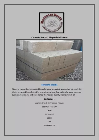
International Journal of Trend in Scientific Research and Development (IJTSRD) ISSN: 2456-6470 Table 8: Aggregate impact value Wt of sample that passed through 2.36mm sieve Wt of sample taken Aggregate impact value Permissible value IS:2386-1963 Should not be greater than 30% Remarks Strong aggregates 400g 65g 16.25% MIXING AND CASTING As per IS 2185 (PART 1): 2005, the concrete mix used for blocks shall not be richer than one part by volume of cement to 6 parts by volume of combined aggregates before mixing. So nominal mix M15 is used. A proper mixer has been used to mix the ingredients. The mix obtained is then filled in steel moulds in three layers. Vibrating table is used to achieve proper compaction. This prevents formation of air bubbles. Fig.13: Hollow blocks after casting BREAK UP OF MATERIALS USED FOR EACH BLOCK In order to find the volume of each block, analysis of dimensions of each block is done and the conclusion is like, that there are two types of keys/grooves present, viz trapezoidal keys/groves that are present sideways and rectangular keys /grooves that are present on top or bottom of blocks. Volume of rectangular keys / grooves need not to be calculated as there are same number of rectangular keys and grooves present on each block. Volume of each rectangular key/groove = ?? Also from section 4.5, we can calculate quantity of material for 1m3 of wet concrete. 1.57 m3 of concrete = .224m3 cement 1m3 of concrete = .??? 1.57 m3 of concrete = .448 m3 sand 1m3 of concrete = .??? 1.57 m3 of concrete = .897 m3 coarse aggregates 1m3 of concrete = .??? BREAK UP OF MATERIALS USED FOR TYPE- A Type A has one key and one groove. It contains one hollow portion with dimensions 12? × .3? × .2?. Net volume = [(.4 × .2) − (.12 × .3)] × .2 = .0088m3 Volume of cement for .0088m3 concrete = .0088×.1426 = 1.2548× 10⁻³ m3 1 m3 of cement = 1440 kg 1.2548× 10⁻³ m3 of cement = 1.2548× 10-3 ×1440 = 1.806 kg Volume of sand for .0088m3 concrete = .0088×.2853 = 2.51064× 10⁻³ m3 1 m3 of sand = 1600 kg 2.51064× 10⁻³ m3 of sand = 2.51064× 10-3 ×1600 = 4.017 kg ?(.06 + .04) × .02? × .2 = .0002 m3 ?.??= .1426m3 cement ?.??= .2853 m3 sand ?.??= .5713 m3 coarse aggregates @ IJTSRD | Available Online @ www.ijtsrd.com | Volume – 2 | Issue – 5 | Jul-Aug 2018 Page: 1857
International Journal of Trend in Scientific Research and Development (IJTSRD) ISSN: 2456-6470 Volume of coarse aggregates for .0088m3 concrete=.0088×.5713=5.0274× 10⁻³ m3 1m3 of coarse aggregates = 1560 kg 5.0274× 10⁻³ m3 of coarse aggregates = 5.0274× 10-3 ×1560 = 7.84kg Quantity of water for 1.806kg of cement= water-cement ratio × quantity of cement = .5× 1.806 = .903 kg or .903 litres BREAK UP OF MATERIALS USED FOR TYPE- B Type A has one key and one groove. It contains two hollow portion with dimensions .1? × .12? × .2?. Net volume = [(.4 × .2) − 2(.12 × .1)] × .2 = .0112m3 Volume of cement for .0112m3 concrete = .0112×.1426 = 1.597× 10⁻³ m3 1 m3 of cement = 1440 kg 1.597× 10⁻³ m3 of cement = 1.597× 10-3 ×1440 = 2.23 kg Volume of sand for .0112m3concrete = .0112×.2853 = 3.195× 10⁻³ m3 1 m3 of sand = 1600 kg 3.195× 10⁻³ m3 of sand = 3.195× 10-3 ×1600 = 5.112kg Vol. of coarse aggregates for .0112m3 concrete=.0112m3×.5713=6.39× 10⁻³ m3 1m3 of coarse aggregates = 1560 kg 6.39× 10⁻³ m3 of coarse aggregates = 6.39× 10-3 ×1560 = 9.9kg Quantity of water for 2.23kg of cement = water-cement ratio × quantity of cement = .5× 2.23 = 1.15 kg or 1.15 litres BREAK UP OF MATERIALS USED FOR TYPE- C (FEMALE) The dimensions and shape of type C (female) is same as that of type A except there are two more trapezoidal grooves present. So the volume of these two grooves need to be subtracted. Net volume = vol. of Type A−2(vol. of trap. groove) =.0088−2(.0002) = .0084 m3 Volume of cement for .0084 m3 concrete = .0084 ×.1426 = 1.19× 10⁻³ m3 1 m3 of cement = 1440 kg 1.19× 10⁻³ m3 of cement = 1.19× 10-3 ×1440 = 1.72kg Volume of sand for .0084 m3concrete = .0084 ×.2853 = 2.39× 10⁻³ m3 1 m3 of sand = 1600 kg 2.39× 10⁻³ m3 of sand = 2.39× 10-3 ×1600 = 3.83kg Vol. of coarse aggregates for .0084 m3 concrete=.0084 m3×.5713=4.79× 10⁻³ m3 1 m3 of coarse aggregates = 1560 kg 4.79× 10⁻³ m3 of coarse aggregates = 4.79× 10-3 ×1560 =7.48kg Quantity of water for 1.72 kg of cement = water-cement ratio × quantity of cement = .5× 1.72 = .86 kg or .86 litres @ IJTSRD | Available Online @ www.ijtsrd.com | Volume – 2 | Issue – 5 | Jul-Aug 2018 Page: 1858
International Journal of Trend in Scientific Research and Development (IJTSRD) ISSN: 2456-6470 BREAK UP OF MATERIALS USED FOR TYPE- C (MALE) The dimensions and shape of type C (male) is same as that of type A except there are two more trapezoidal keys present. So the volume of these two keys need to be added. Net volume = vol. of Type A+2(vol. of trap. key) =.0088+2(.0002) = .0092 m3 Volume of cement for .0092 m3 concrete = .0092 ×.1426 = 1.31× 10⁻³m3 1 m3 of cement = 1440 kg 1.31× 10⁻³ m3 of cement = 1.39× 10-3 ×1440 = 1.89kg Volume of sand for .0092 m3concrete = .0092 ×.2853 = 2.62× 10⁻³ m3 1 m3 of sand = 1600 kg 2.62× 10⁻³ m3 of sand = 2.62× 10-3 ×1600 = 4.19kg Vol. of coarse aggregates for .0092 m3 concrete=.0092 m3×.5713=5.25× 10⁻³ m3 1 m3 of coarse aggregates = 1560 kg 5.25× 10⁻³ m3 of coarse aggregates = 5.25× 10-3 ×1560 =8.19 kg Quantity of water for 1.89 kg of cement = water-cement ratio × quantity of cement = .5× 1.89 = .94 kg or .94 litres. BREAK UP OF MATERIALS USED FOR TYPE- D (FEMALE) The dimensions and shape of type D (female) is same as that of type B except there are two more trapezoidal grooves present. So the volume of these two grooves need to be subtracted. Net volume = vol. of Type B−2(vol. of trap. groove) =.0112−2(.0002) = .0108 m3 Volume of cement for .0108 m3 concrete = .0108×.1426 = 1.54× 10⁻³ m3 1 m3 of cement = 1440 kg 1.54× 10⁻³ m3 of cement = 1.54× 10-3 ×1440 = 2.21kg Volume of sand for .0108 m3concrete = .0108 ×.2853 = 3.08× 10⁻³ m3 1 m3 of sand = 1600 kg 3.08× 10⁻³ m3 of sand = 3.08× 10-3 ×1600 = 4.92kg Vol. of coarse aggregates for .0108 m3 concrete=.0108 m3×.5713=6.17× 10⁻³ m3 1 m3 of coarse aggregates = 1560 kg 6.17× 10⁻³ m3 of coarse aggregates = 6.17× 10-3 ×1560 =9.62kg Quantity of water for 2.21 kg of cement = water-cement ratio × quantity of cement = .5× 2.21 = 1.105 kg or 1.105 litres. BREAK UP OF MATERIALS USED FOR TYPE- D (FEMALE) The dimensions and shape of type D (male) is same as that of type B except there are two more trapezoidal keys present. So the volume of these two keys need to be added. Net volume = vol. of Type B+2(vol. of trap. keys) =.0112+2(.0002) = .0116 m3 Volume of cement for .0116m3 concrete = .0116×.1426 = 1.65× 10⁻³ m3 1 m3 of cement = 1440 kg 1.65× 10⁻³ m3 of cement = 1.65× 10-3 ×1440 = 2.37kg @ IJTSRD | Available Online @ www.ijtsrd.com | Volume – 2 | Issue – 5 | Jul-Aug 2018 Page: 1859
International Journal of Trend in Scientific Research and Development (IJTSRD) ISSN: 2456-6470 Volume of sand for .0116 m3concrete = .0116×.2853 = 3.3× 10⁻³ m3 1 m3 of sand = 1600 kg 3.3× 10⁻³ m3 of sand = 3.3× 10-3 ×1600 = 5.29kg Vol. of coarse aggregates for .0116 m3 concrete=.0116 m3×.5713=6.62× 10⁻³ m3 1 m3 of coarse aggregates = 1560 kg 6.62× 10⁻³ m3 of coarse aggregates = 6.62× 10-3 ×1560 =10.33kg Quantity of water for 2.46 kg of cement = water-cement ratio × quantity of cement = .5× 2.37 = 1.18 kg or 1.18 litres. COMPRESSIVE STRENGTH OF BLOCKS COMPRESSIVE STRENGTH OF TYPE-A Load bearing area = (400×200) (300×120) = 44000mm2 AGE (DAYS) (KN) STRENGTH (MPa) 7 155 3.52 14 244 5.54 28 283 6.43 COMPRESSIVE STRENGTH OF TYPE-B Load bearing area = (400×200)(2×100×120) = 56000mm2 AGE (DAYS) (KN) STRENGTH (MPa) 7 317 5.6 14 380 6.7 28 454 8.1 COMPRESSIVE STRENGTH OF (FEMALE) Load bearing area = (400×200)(300×100) 2000= 48000mm2 AGE (DAYS) (KN) STRENGTH (MPa) 7 210 4.37 14 255 5.31 28 324 6.75 28 297 7 COMPRESSIVE (FEMALE) Load bearing area = (400×200)(2×100×100) 2000= 58000mm2 AGE (DAYS) (KN) 7 321 14 448 28 510 COMPRESSIVE STRENGTH (MALE) Load bearing area = (400×200)(2×100×120)+20 00= 58000mm2 AGE (DAYS) (KN) 7 303 14 430 28 484 COMPRESSIVE STRENGTH OF PRISMS As per IS 1905: 1987, for compressive strength, prism shall be at least 40 cm high and shall have a height to thickness ratio of at least 2 but not more than 5. In case of block work if h/t value is more than 2, then the strength values indicated by the test are corrected by multiplying with the factor. COMPRESSIVE STRENGTH OF PRISM A In PRISM-A the two TYPE-A blocks are interlocked in a stretcher bond as shown in the figure. And the same combination of two is staked on another, Then they are placed on a loading frame and uniformly distributed load is applied to the prism in the form of compression load. STRENGTH OF TYPE-D PEAK LOAD COMPRESSIVE PEAK LOAD COMPRESSIVE STRENGTH (MPa) 5.5 7.7 8.7 OF TYPE-D PEAK LOAD COMPRESSIVE PEAK LOAD COMPRESSIVE STRENGTH (MPa) 5.2 7.4 8.34 TYPE-C PEAK LOAD COMPRESSIVE COMPRESSIVE (MALE) Load bearing area = (400×200)(300×120) + 2000 = 42000mm2 AGE (DAYS) (KN) 7 202 14 240 STRENGTH OF TYPE-C PEAK LOAD COMPRESSIVE STRENGTH (MPa) 4.8 5.7 @ IJTSRD | Available Online @ www.ijtsrd.com | Volume – 2 | Issue – 5 | Jul-Aug 2018 Page: 1860
International Journal of Trend in Scientific Research and Development (IJTSRD) ISSN: 2456-6470 Load bearing area = 88000mm2 Height of prism = 400mm Width of prism = 200mm Load bearing area (mm) load (KN) strength A 88000 495 5.62 Ultimate Compressive Correction factor 1 Modified compressive strength 5.62 PRISM h/t 2 COMPRESSIVE STRENGTH OF PRISM B In this prism two TYPE-B blocks are placed on one another with keys pointing upwards interlocking in one another. The keys of top block are in direct contact with the load cell, so in order to provide uniform compressive loading on the whole block, the packing plates are used to make the top surface of prism uniform to get accurate results. Load bearing area = 56000mm2 Height of prism = 420mm Width of prism = 200mm Compressive strength (MPa) 7.14 Modified compressive strength (MPa) 7.28 Load bearing area (mm) Ultimate load (kN) h/t ratio Correction factor PRISM B 56000 400 2 1.02 COMPRESSIVE STRENGTH OF PRISM C1 In this prism the TYPE-C blocks (both male and female) are interlocked on front and rare side making a width of 400mm.Other three same arrangements are stacked on this one making the total height of 800mm. Since there are no top-bottom keys, so no packing plates are needed. Load bearing area = 50000 + 40000 = 90000mm2 Height of prism = 800mm Width of prism = 400mm Ultimate load (kN) (MPa) C1 90000 710 7.8 COMPRESSIVE STRENGTH OF PRISM C2 In this prism in addition to PRISM-C1, one more Type-C female block is added as a header but in the same course which gets interlocked to the end keys of other two blocks. Four same combinations are stacked on each other. No packing plates are required as the top surface is smooth. So load is directly applied on the three block prism. Compressive strength Load bearing area (mm) h/t ratio Correction factor Modified compressive strength (MPa) PRISM 2 1 7.8 @ IJTSRD | Available Online @ www.ijtsrd.com | Volume – 2 | Issue – 5 | Jul-Aug 2018 Page: 1861
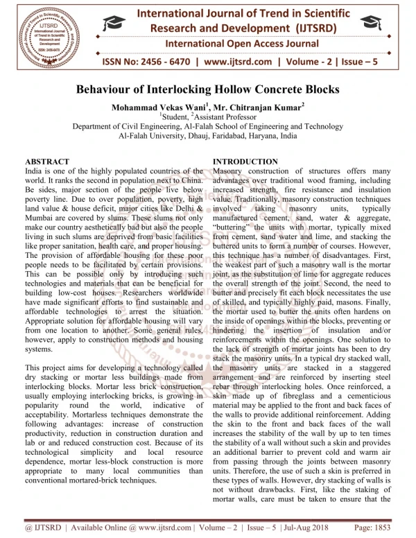
International Journal of Trend in Scientific Research and Development (IJTSRD) ISSN: 2456-6470 Load bearing area = 50000 + 40000 +50000 = 140000mm2 Height of prism = 800mm Width of prism = 400mm PRI SM area (mm) C2 140000 STIFFNESS OF PRISMS OBSERVATIONS OF PRISM IN SHEAR LOADING ULTIMA TE LOAD (KN) NT (mm) Prism A Prism B Prism C1 Prism C2 Load bearing Ultimate load (kN) 700 Compressive strength (MPa) 5 h/t ratio 2 Correction factor 1 Modified compressive strength (MPa) 5 MAXIMUM DISPLACEME STIFFNE SS (KN/mm) PRIS M 275 18.3 15 293 16.2 18.74 372 20.7 17.97 380 19.86 19.13 CONCLUSION AND FUTURE SCOPE While looking at the results obtained from the different tests that i did on block patterns and prisms, i can notice the strength is much better than ordinary concrete blocks and clay bricks. It is evident from the above results that the compressive strength of interlocking hollow blocks is in the range of 6-9MPa, which is better than the compressive strength of ordinary existing hollow blocks and bricks. A table to compare their strength is given below @ IJTSRD | Available Online @ www.ijtsrd.com | Volume – 2 | Issue – 5 | Jul-Aug 2018 Page: 1862
International Journal of Trend in Scientific Research and Development (IJTSRD) ISSN: 2456-6470 Comparison of compressive strength of blocks with bricks &ordinary units REFERENCES 1.Overview of concrete block wall construction without mortar by IJIRST Volume 03/issue 10/March 2017 ISSN (online) 2349-6010. Compressive strength (MPa) 10 6.8 3.4 6.43 8.1 6.75 7 8.7 8.34 Type Ist class traditional brick 2nd class traditional brick Common building brick TYPE -A TYPE B TYPE C female TYPE C male TYPE D female TYPE D male 2.Seismic analysis of interlocking blocks as infill wall by a journal published in IRJET: e- ISSN: 2395-0056; p-ISSN: 2395- 0072, Volume 03 issue 10/oct-2016. 3.Structural behavior of interlocking concrete blocks ISSN (e): 2250-3021, ISSN (p): 2278- 8719 IOSR journal 4.Journal of Civil Engineering and Environmental Technology Print ISSN: 2349-8404; Online ISSN: 2349-879X; Volume 1, Number 5; August, 2014 pp. 114–118. From the data available it is concluded that 1.The compressive strength interlocking blocks is 6– 9 MPa and that of prisms is 5– 8MPa which is almost same. 2.The compressive strength of individual blocks is much better than traditional briks and concrete blocks. 3.The stiffness of prism C1 is maximum 4.The interlocking blocks results in speedier construction thereby saving money and time. 5.It eliminates mortar bed completely which otherwise proves to be the failure bed for diagonal tension. 6.It results in a labor cost reduction of up to 80%. Because these are self aligning thus reduce time wasting adjustments. 7.Hollow nature makes these blocks perfect for sound and heat insulation. FUTURE SCOPE The interlocking blocks discussed in our project can be modified in future by: 1.The use of reinforcing in the pins provided. 2.Use of steel strips or steel plates in pins. 3.Use of lateral tie rods grouted to the blocks to increase their integrity. 4.Use of vertical rods in the hollow portion provided which are then held in position by grouting. This increases integrity between different coarses. 5.Use of such rods increases the tensile strength of rods thereby increasing their overall strength and hence making them useful for seismic areas as well. 6.Use of light weight materials like fly ash so that blocks can be lifted, transported and placed easily 5.Interlocking brick design-paradigm for sustainable construction. International Journal for Research in Applied Science & Engineering Technology (IJRASET) www.ijraset.com Volume 3 Issue I, January 2015 ISSN: 2321-9653 6.Blocks for building walling systems. IJRET: International Journal of Research in Engineering and Technology e ISSN: 2319-1163 | p ISSN: 2321-7308. 7.Compression performance of walls of interlocking bricks made of iron ore by-product and cement. International Journal of Civil & Environmental Engineering IJCEE IJENS Vol:13 No:03 8.IS 2185 Part 1:1985 Concrete masonry units specification. 9.IS 4031(part 5):2005 Methods of physical testing for cement. 10.IS 383:1970 specifications for coarse and fine aggregates. 11.IS 2386:1963 methods for tests for aggregates for concrete. 12.IS 1905:1987 code for practice for structural use of unreinforced masonry. 13.Development of innovative building blocks. IOSR Journal of Engineering. E-ISSN: 2278-1684, p-ISSN: 2320- 334X. Mechanical and Civil @ IJTSRD | Available Online @ www.ijtsrd.com | Volume – 2 | Issue – 5 | Jul-Aug 2018 Page: 1863