Download
1 / 3
30 likes | 49 Views
The basic concept in designing of any power lines in transmission of ac dc power with power upgrading using UPFC is proposed through a single circuit ac transmission line. In this proposal certain limitation are their due to the use of ground as return path. More ever the instantaneous value of each conductor voltage with respect to ground becomes higher than the Line Line voltage. By using UPFC that is unified power flow controller we can make it possible to handle practically all power flow control and transmission line compensation problem which provide functional flexibility in power which is not possible by the use of conventional thyristor control system. In this paper we have design UPFC to improve stability of power oscillation that are caused due to non linearity of the load. MATLAB Simulink model has been develop for this concept. Sandeep Sonwane | Pratik Ghutke "Power Upgrading of Transmission Line by Combining AC-DC Transmission and Analysis of UPFC" Published in International Journal of Trend in Scientific Research and Development (ijtsrd), ISSN: 2456-6470, Volume-3 | Issue-4 , June 2019, URL: https://www.ijtsrd.com/papers/ijtsrd23691.pdf Paper URL: https://www.ijtsrd.com/engineering/electrical-engineering/23691/power-upgrading-of-transmission-line-by-combining-ac-dc-transmission-and-analysis-of-upfc/sandeep-sonwane<br>

E N D
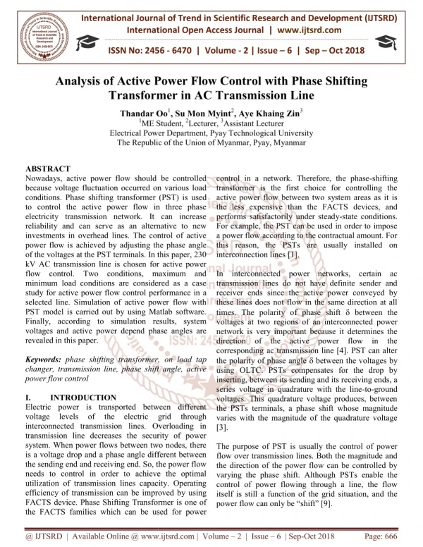
International Journal of Trend in Scientific Research and Development (IJTSRD) Volume: 3 | Issue: 4 | May-Jun 2019 Available Online: www.ijtsrd.com e-ISSN: 2456 - 6470 Power Upgrading of Transmission Line by Combining AC-DC Transmission and Analysis of UPFC Sandeep Sonwane1, Pratik Ghutke2 1PG Student, 2Assistant Professor 1,2Department of Electrical Engineering, T.G.P.C.E.T College, Nagpur, Maharashtra, India How to cite this paper: Sandeep Sonwane | Pratik Ghutke "Power Upgrading of Transmission Line by Combining AC-DC Transmission and Analysis of UPFC" Published in International Journal of Trend in Scientific Research and Development (ijtsrd), ISSN: 2456- 6470, Volume-3 | Issue-4, June 2019, pp.387-389, URL: https://www.ijtsrd.c om/papers/ijtsrd23 691.pdf Copyright © 2019 by author(s) and International Journal of Trend in Scientific Research and Development Journal. This is an Open Access article distributed under the terms of the Creative Commons Attribution License (CC BY 4.0) (http://creativecommons.org/licenses/ by/4.0) At the same time electric power demand continues to grow and also building of the new generating units and transmission circuits is becoming more difficult because of economic and environmental reasons. Therefore, power utilities are forced to relay on utilization of existing generating units and to load existing transmission lines close to their thermal limits. However, stability has to be maintained at all times. Hence, in order to operate power system effectively, without reduction in the system security and quality of supply, even in the case of contingency conditions such as loss of transmission lines and/or generating units, which occur frequently, and will most probably occur at a higher frequency under deregulation, a new control strategies need to be implemented. ABSTRACT The basic concept in designing of any power lines in transmission of ac-dc power with power upgrading using UPFC is proposed through a single circuit ac transmission line. In this proposal certain limitation are their due to the use of ground as return path. More ever the instantaneous value of each conductor voltage with respect to ground becomes higher than the Line-Line voltage. By using UPFC that is unified power flow controller we can make it possible to handle practically all power flow control and transmission line compensation problem which provide functional flexibility in power which is not possible by the use of conventional thyristor control system. In this paper we have design UPFC to improve stability of power oscillation that are caused due to non- linearity of the load. MATLAB -Simulink model has been develop for this concept. Keywords: Control system, MATLAB, UPFC, power devices, Series converter, Shunt converter I. INTRODUCTION The power system is an interconnection of generating units to load centers through high voltage electric transmission lines and in general is mechanically controlled. It can be divided into three subsystems: generation, transmission and distribution subsystems. Until recently all three subsystems were under supervision of one body within a certain geographical area providing power at regulated rates. In order to provide cheaper electricity the deregulation of power system, which will produce separate generation, transmission and distribution companies, is already being performed. IJTSRD23691 behaves as an ideal synchronous machine, i.e. generates fundamental frequency three-phase balanced sinusoidal voltages of controllable amplitude and phase angle. It can internally generate both inductive and capacitive reactive power. If coupled with an appropriate energy storage device, i.e. dc storage capacitor, battery, etc, SVS is able to exchange real power with the ac system. The SVS can be implemented by the use of the voltage sourced- converters (VSC). The SVS can be used as shunt or series compensator. If operated as a reactive shunt compensator it is called static condenser (STATCON), operated as a reactive series compensator it is called static synchronous series compensator (SSSC). A special arrangement of two SVSs, one connected in series with the ac system and the other one connected in shunt, with common dc terminals is called Unified Power Flow Controller (UPFC). It represents series - shunt type of controller. The Interline Power Flow Controller (IPFC) is recently introduced series-series type of controller. It consists of two or more SSSCs coupled through a common DC link. IPFC provides independently controllable reactive series compensation of each selected line as well as transfer of real power between the compensated lines. In the late 1980s the Electric Power Research Institute (EPRI) has introduced a new technology program known as Flexible AC Transmission System (FATCS) [4]. The main idea behind this program is to increase controllability and optimize the utilization of the existing power system capacities by replacing mechanical controllers by reliable and high- speed power electronic devices. The latest generation of FACTS controllers is based on the concept of the solid state synchronous voltage sources (SVSs) introduced by L. Gyugyi in the late 1980s [5]. The SVS The advantages of SVS based compensators over mechanical and conventional thyristor compensators are @ IJTSRD | Unique Paper ID - IJTSRD23691 | Volume – 3 | Issue – 4 | May-Jun 2019 Page: 387
International Journal of Trend in Scientific Research and Development (IJTSRD) @ www.ijtsrd.com eISSN: 2456-6470 ?improved operating and performance characteristics ?uniform use of same power electronic device in different compensation and control applications ?Reduced equipment size and installation labor. 3.Phase-shift control- Phase shift by UPFC is in the state which finds phase change but its amplitude doesn’t change. Multipurpose control of UPFC; it may control the power at the same time and compensation is carried out with respect to terminal voltage and line series compensation change or alteration in phase-shift angle. II. ?Using the concept of the control system a power system is taken to implement the use of UPFC. The two modes i.e. the power flow control and the voltage injection mode are simulated in SIMULINK to see the effect of UPFC on a power system. Study is carried out to verify the utility of FACT device. ?Its application study the steady-state and dynamic performance of a unified power flow controller (UPFC) used to relieve power congestion in a transmission system. ?The load flow analysis and the single line diagram simulation are done on power flow simulator. ?This software(MATLAB) helps to calculate the power flow, the voltage at each bus and the cost effectiveness of the system.Based on test power system. ?The Optimal Power Flow Analysis (OPF) has been implemented for various case studies. This case is considered in order to investigate the effect of Test power system absence of UPFC in comparison with presence of UPFC in OPF. Scope of Present Work The power circuit of UPFC is shown below Fig1. Basic power circuit of UPFC V. Simulation Model In this project, I am going to monitor the power of the system especially known as industries and controlling the power line using power factor. Here the current transformers and potential transformers are widely used for analyzing the performance of the power and it is given to the circuit .It is known that electricity comes in our home is not stable in nature. There are many fluctuations, raise and falls, and spikes in this current. This unstable current may damage instruments. The fluctuating current wastes the electric current in the form of heat energy. This heat energy not only gets wasted to the atmosphere, but also harms the appliances and wiring circuit. Fig2.Simulation of model of system VI. Simulation Model of UPFC III. In power system transmission, it is desirable to maintain the voltage magnitude, phase angle and line impedance. Therefore, to control the power from one end to another end, this concept of power flow control and voltage injection is applied .Modeling the system and studying the results have given an indication that UPFC are very useful when it comes to organize and maintain power system. Aim and Objectives In this study the effects of UPFC locations are investigated on voltage profile and transmission lines power flow as active and reactive power are analyzed. Fig3.Simulation model of UPFC VII. Results Following Objectives are made: 1.Power flow control to be achieved and congestion Should be less 2.Transient stability Should be improved 3.Faster Steady State achievement 4.Improved Voltage Profile IV. The UPFC consist of a series R-L-C network in bus line. The UPFC is designed consist of three important methods. 1.It can control the terminal voltage of the line. 2.It can perform series compensation. Designing of UPFC Fig4. Result of thyristers. @ IJTSRD | Unique Paper ID - IJTSRD23691 | Volume – 3 | Issue – 4 | May-Jun 2019 Page: 388
International Journal of Trend in Scientific Research and Development (IJTSRD) @ www.ijtsrd.com eISSN: 2456-6470 6.Different strategies could be tested and implemented in an attempt to achieve a less time consuming process and gain better understanding of heuristic optimization techniques applicability to various power system phenomena. X. References [1]L. Gyugyi, C.D. Schauder, S.I. Williams, T.R. Reitman, D.R.Torgerson and A. Edris, 1995, “The Unified Power Flow Controller:A new transmission control”, IEEE Trans. On Power Delivery, 10(2), pp. 1085-1095. VIII. The purpose of applying FACTs tools is to removes the oscillation of the power angle and increase stability of the system by upgrading the power more-ever the UPFC helps in providing the quality power without damping and controlling the voltage effectively at the non-linear load side. UPFC is one of the index tools of AC transfer system having promising capabilities for controlling the parameters of utilizing the transfer system in the steady state and the transient state of system. IX. Future scope ?This work deals with modeling and simulation of 30 bus system using MATLAB simulink.. ?This work has covered power quality in 30 bus system using UPFC. ?The work may be extended to sixty four bus system. Hardware implementation is beyond the scope of this work. ?Laboratory model for the hardware may be implemented using Digital Signal Processor (DSP). ?114 Multibus system with multiple FACTS controllers may be studied to observe the power quality improvement. ?Closed loop system using Neural network or genetic algorithm can be studied in future. Research and development is a non-stopping process. For any research work carried out, there is always a possibility for better chances of improvement and lot many avenues opened for further work. As a result of the investigations carried out in the area of power system stability improvement with FACTS controllers, following aspects are identified for further scope of research work. 1.The present work can be extended to power system with generalized TCSC, UPFC and Interline Power Flow Controller (IPFC). 2.The system investigated has been limited up to a three- machine power system. It would be desirable to extend the proposed approach for larger and more realistic systems. 3.The present work can be extended for STATCOM and SSSC with energy storage such as battery Energy Storage System (BESS) and Superconducting Magnetic Storage (SMSS) for enhancing power system stability. 4.The present work can be extended for damping of torsional oscillations. 5.Stability issues for a distribution network with different types of distributed generation sources and FACTS devices could be examined and FACTS-based controllers could be designed for improving the stability in presence of different types of distributed generations. Conclusion approach to power [2]M. Noroozian, L. Angquist, M. Ghandhari, G. Andersson, 1997, “Use ofUPFC for Optimal Power Flow Control,”IEEE Transactions on Power Delivery 12(4), pp. 1629-1634. [3]B.A. Renz, A. Keri, A.S. Mehraben, C. Schauder, E. Stacey, I.Kovalsky, L. Gyugyi, and A. Edris, 1999, “AEP Unified Power Flow Controller Performance”, IEEE Trans. o Power Delivery, 14(4), pp.1374-1381. [4]L.Gyugi, Unified power flow controller concept for flexible ACtransmission systems, IEE Proceedings-C, Vol.139, No.4, July 1992,pp. 323-331. [5]K.S. Verma,, S.N. Singh, H.O. Gupta, Location of unified power flowcontroller for congestion management, Electric Power Systems Research 58 (2001) 89-96. [6]M. Noroozian, L. Angquist, M. Ghandhari, G. Andersson, 1997, “Use of UPFC for Optimal Power Flow Control,” IEEE Transactions on Power Delivery, 12(4), pp. 1629- 1634. [7]D. Murali, Dr. M. Rajaram, Active and Reactive Power Flow Controlusing FACTS Devices, International Journal Of ComputerApplications (0975 – 8887), Volume 9 – No.8, November 2010. [8]S. Tara Kalyani, G. Tulasiram Das, Simulation of Real and ReactivePower Flow Control with UPFC Connected to a Transmission Line, International Journal Of Computer Applications, 2008, (16-22) [9]Xiao-Ping Zhang,Christian Rehtouz, Bikash Pal, Flexible AC Transmission Systems: Modeling and Control, Springer-Verlag Berlin Heidelberg, 2006.Papers from Conference Proceedings (Published) [10]Bhanu KOTAMARTI. S. B.Sankar, PINDIPROLU. V. Haranath, “17th International Distribution,” CIRED, Barcelona 2003, Session 5 Paper No 19. CHENNAPRAGADA Venkata Krishna, Conference on Electricity @ IJTSRD | Unique Paper ID - IJTSRD23691 | Volume – 3 | Issue – 4 | May-Jun 2019 Page: 389