Download
1 / 6
60 likes | 81 Views
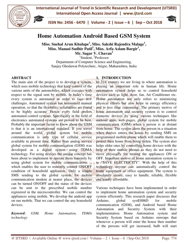
In this paper, describes about how to control home appliances, auto door sliding motor, fan and lighting using GSM technology by using android application through android mobile phone. Performing of these tasks with a single android device makes every faster because the android makes SMS communication. This paper serve as a basic structure of the communication control system. The programming is done door operating system, hedge light bulbs and fan and light bulbs inside the home. Arduino Uno, Sensors and serial communicating devices are incorporated and synchronized with the personal computer. Mrs Khin Ei Ei Khine | Mr Nay Soe Shwe | Mr Aung Myo Naing "GSM Based Home Appliance Control System" Published in International Journal of Trend in Scientific Research and Development (ijtsrd), ISSN: 2456-6470, Volume-3 | Issue-5 , August 2019, URL: https://www.ijtsrd.com/papers/ijtsrd26743.pdf Paper URL: https://www.ijtsrd.com/engineering/electrical-engineering/26743/gsm-based-home-appliance-control-system/mrs-khin-ei-ei-khine<br>

E N D
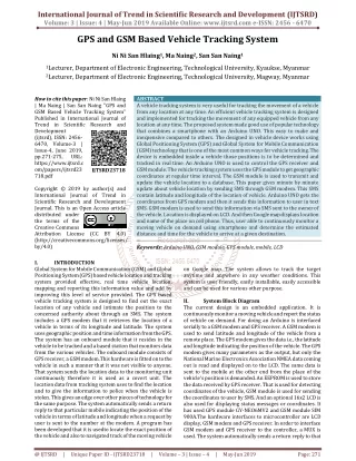
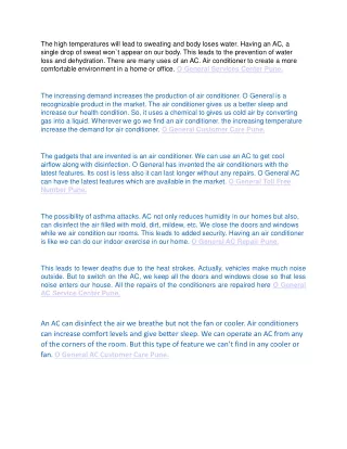
International Journal of Trend in Scientific Research and Development (IJTSRD) Volume 3 Issue 5, August 2019 Available Online: www.ijtsrd.com e-ISSN: 2456 – 6470 GSM Based Home Appliance Control System Mrs Khin Ei Ei Khine, Mr Nay Soe Shwe, Mr Aung Myo Naing Master of Engineering, Technological University, Hmawbi, Yangon, Myanmar How to cite this paper: Mrs Khin Ei Ei Khine | Mr Nay Soe Shwe | Mr Aung Myo Naing "GSM Based Home Appliance Control System" Published in International Journal of Trend in Scientific Research and Development (ijtsrd), ISSN: 2456- 6470, Volume-3 | Issue-5, August 2019, pp.1675-1680, https://doi.org/10.31142/ijtsrd26743 Copyright © 2019 by author(s) and International Journal of Trend in Scientific Research and Development Journal. This is an Open Access article distributed under the terms of the Creative Commons Attribution License (CC (http://creativecommons.org/licenses/by /4.0) But mobile phones are not only used for the calling and sending SMS purposes but also new ideas is generated and techniques from it that further enhance it capabilities. Having wireless control of almost all the things in a person’s life is a growing interest and many systems are providing such control. This idea has designed a control system which is based on the GSM technology that effectively allows control from a remote area to the desired location. Because of this system, there is no need for a person to physically present to switch on/off the electrical appliances. This paper represent remotely controlled smart home automation system, for monitoring and controlling of the home light, hedge light, fan and sliding door by using GSM phone inside and outside the home. [1] The SMS received by the receiver is transmitted to the Arduino Uno which reads the message and controls the appropriate device. The SMS received by the receiver is transmitted to the Arduino Uno which reads the message and controls the appropriate device. The primary goal is to discuss home automation technology, lifetime is getting easier and simpler on all side in life. This technology proposed to control the home GSM network. The user commands are transferred to a server, processes the user commands and sends them to the relevant units. The home server is built upon a SMS mobile cell module. The system makes use of Arduino Uno for home appliances control. It makes use of GSM for control of the appliances in terms of SMS based system.[2] ABSTRACT In this paper, describes about how to control home appliances, auto door sliding motor, fan and lighting using GSM technology by using android application through android mobile phone. Performing of these tasks with a single android device makes every faster because the android makes SMS communication. This paper serve as a basic structure of the communication control system. The programming is done door operating system, hedge light- bulbs and fan and light-bulbs inside the home. Arduino Uno, Sensors and serial communicating devices are incorporated and synchronized with the personal computer. KEYWORDS: SMS communication, Control System, Sensor, GSM technology, android mobile phone, Arduino Uno 1.INTRODUCTION In recent years, the wireless communication is increasing day by day. There is a huge advancement in the communication sector. Any new facilities home appliances that promise to enhance the life style is grabbed by the consumers. The more such facilities and appliances are improved, it becomes inevitable to have easy and convenient methods and means to control and operate these appliances. Almost all people nowadays have access to mobile phones and thus the world has indeed become a global village. At any given moment, any person across the world is contacted with the help of a mobile phone. IJTSRD26743 BY 4.0) 2.SYSTEM DESCRIPTION The system has two parts, namely; hardware and software. The hardware architecture consists of 1.Arduino Uno (ATmega328) 2.GSM Shield SIM900A Moderm 3.Limit Switch Sensor 4.8-channel Relay Module 5.7805 Voltage Regulator 6.L293 Motor Driver 7.Diode 8.Capacitor 9.Resistor 10.LED 11.Printed Circuit Board (PCB) 2.1 Arduino Uno (ATmega328) The Arduino Uno is a microcontroller board based on the (AT mega 328) as shown in figure-1. It has 14 digital input/output pins (of which 6 can be used as PWM outputs), 6 analog inputs, a 16 MHz crystal oscillator, a USB connection, a power jack, an ICSP header, and a reset button. It contains everything needed microcontroller; simply connect it to a computer with a USB cable or power it with an AC-to-DC adapter or battery to get started. This board operates in 5V 40-50mA. This paper has used an adapter with the Arduino Uno (ATmega328) while provide the power supply to all the components. to support the @ IJTSRD | Unique Paper ID – IJTSRD26743 | Volume – 3 | Issue – 5 | July - August 2019 Page 1675
International Journal of Trend in Scientific Research and Development (IJTSRD) @ www.ijtsrd.com eISSN: 2456-6470 2.3 In electrical engineering a limit switch is a switch operated by the motion of a machine part or presence of an object. It used for controlling machinery as part of a control system, as a safety interlocks, or to count objects passing a point. A limit switch is an electromechanical device that consists of an actuator mechanically linked to a set of contacts. When an object comes into contact with the actuator, the device operates the contacts to make or break an electrical connection. Limit switches are used in a variety of applications and environments because of their ruggedness, ease of installation, and reliability of operation. It is determined the presence or absence, passing, positioning, and end of travel of an object. The limit switch sensor is shown in figure 3. Limit Switch Sensor Figure1: Arduino Uno (ATmega328) Table-1 Arduino Uno Technical Specifications A T mega 328 P 8 bit AVR family micro controller Operating Voltage 5V Recommended Input Voltage Input Voltage Limits 6-20V Analog Input Pins 6 (A0 – A5) 14 (Out of which 6 provide PWM output) DC Current on I/O Pins DC Current on 3.3V Pin 32 KB (0.5 KB is used for Bootloader) SRAM 2 KB EEPROM 1 KB Frequency (Clock Speed) 2.2 GSM Shield SIM900A Module GSM module is used in many communication devices which are based on GSM (Global System for Mobile Communication) technology. GSM module only understands AT commands and respond accordingly. The GSM plays a very important role wireless communication. Features of GSM SIM900A A.Quad-Band 850/900/1800/1900 MHz B.Dual-Band 900/1900 MHz C.GPRS multi-slot class 10/8GPRS mobile station class B D.(d)Compliant to GSM phase 2/2+Class 4 (2W @850/ 900 MHz) E.(e)Class 1 (1W @1800/1900MHz) F.(f)Control via AT commands (GSM 07.07, 07.05 and SIMCOM enhanced AT Commands) G.(g)Low power consumption: 1.5mA (sleep mode) Micro controller 7-12V Digital I/O Pins 40 mA Figure 3.Limit Switch Sensor 50 mA 2.4 The 5V 8-channel relay board used to control various appliances is shown in figure. It is used with or without microcontrollers. Each 5V relay needs 20mA driving current. It has LEDs for indication of output status. 8Channel Relay Module Flash Memory 16MHz Figure4. 8 Channel Relay Module 2.5 Two enable inputs are provided to enable or disable the device independently of the input signals. An additional supply input is provided so that the logic works at lower voltage. These ICs are designed to control 2 DC motors simultaneously. L293D consist of two H-bridge. H-bridge is the simplest circuit for controlling a low current rated motor. We will be referring the motor driver IC as L293D only. L293D has 16pins. In this paper, L293 motor driver are used for running the door motor forward or reversed. Figure 6 shows the pin connection of L293 motor driver. L293 Motor Driver Figure2 GSM SIM900A @ IJTSRD | Unique Paper ID – IJTSRD26743 | Volume – 3 | Issue – 5 | July - August 2019 Page 1676
International Journal of Trend in Scientific Research and Development (IJTSRD) @ www.ijtsrd.com eISSN: 2456-6470 Table2. Pin Function of 7805 voltage regulator Pin No Function 1 Input Voltage ( 5V-18V) 2 Ground ( 0V) 3 Regulated output; 5V (4.8V~ 5.2V) Name Input Ground Output 2.7 A PCB is the board base for physically supporting and wiring the surface-mounted and socketed components in most electronics. PCBs are made by a photolithographic process, in a larger scale version of the way conductive paths in processors are made. Most PCBs are made from fiberglass or glass-reinforced plastics with copper traces. PCBs is single- layer for simple electronic devices. Printed circuit boards for complex hardware, such as computer graphics cards and motherboards, may have up to twelve layers. PCBs are most often green but they can come in any color. Other methods of PCBs manufacturing include silk-screening and CNC- milling. Printed Circuit Board (PCB) Figure5 Pin Connection of L293 Motor Driver Table3. Pin description of L293 Motor Driver PIN NO Enable pin for Motor 1; active high 2 Input 1 for Motor 1 3 Output 1 for Motor 1 4 Ground (0V) 5 Ground (0V) 6 Output 2 for Motor 1 7 Input 2 for Motor 1 Supply voltage for Motors; 9-12V (up to 36V) Enable pin for Motor 2; active high 10 Input 1 for Motor 1 11 Output 1 for Motor 1 12 Ground (0V) 13 Ground (0V) 14 Output 2 for Motor 1 15 Input2 for Motor 1 16 Supply voltage; 5V (up to 36V) FUNCTION NAME 1 Enable 1,2 Input 1 Output 1 Ground Ground Output 2 Input 2 8 Vcc 2 9 Enable 3,4 Input 3 Output 3 Ground Ground Output 4 Input 4 Vcc 1 2.6 7805 is a voltage regulator integrated circuit. It is a member of 78XX series of fixed linear voltage regulator ICs. The voltage source in a circuit may have fluctuations and would not give the fixed voltage output. The voltage regulator IC maintains the outputs voltage at a constant value. The XX in 78XX indicates the fixed output voltage it is designed to provide. 7805 provides +5V regulated power supply. Figure7. Printed Circuit Board 6 7805 Voltage Regulator 3.RESULT AND OPERATION OF CONTROL SYSTEM In this paper, results of the control system be expressed. Arduino Uno (A Tmaeg328) and GSM SIM900A shield are used to control automatic gate door, hedge light, home light and fan circuits. The flow chat control diagram for OPEN and CLOSE, Hedge light ON and OFF, Home Light ON and OFF and Fan ON and Off are shown in figure. In figure 8 , first the system is started read the SMS massage, if the message is Door Open , door motor is opened and then closed with delay time is 2 seconds. If the message is Door Close, door motor is closed and then open with delay time is 2 seconds. In figure 9, the message is checked the Fan ON? If the message is Yes, the Fan is ON and ifNo the message is checked the Hedge LightON? If the message is true, Hedge Light is ON andNo go to B. In figure 10, the message is checked the Home LightON? If the message is true, the Home Light is ON and if No the message is checked the Fan ON? If the message is true, Fan is ON and No go to C. In figure 11, the message is checked the Hedge LightOFF? If the message is true, the Hedge LightOFF and if No the message is checked the Home LightOFF? If the message is true, Home Light is OFF and No go to Loop. Figure6. Pin Diagram of 7805 Voltage Regulator @ IJTSRD | Unique Paper ID – IJTSRD26743 | Volume – 3 | Issue – 5 | July - August 2019 Page 1677
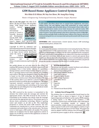
International Journal of Trend in Scientific Research and Development (IJTSRD) @ www.ijtsrd.com eISSN: 2456-6470 Figure10 Flow Chat for GSM based Home Automation System-3 Figure8 Flow Chat for GSM based Home Automation System-1 Figure9 Flow Chat for GSM based Home Automation System-2 Figure11 Flow Chat for GSM based Home Automation System-4 4.GSM Based Home Automation Control Circuit Figure12 Overall circuit diagram for Control System @ IJTSRD | Unique Paper ID – IJTSRD26743 | Volume – 3 | Issue – 5 | July - August 2019 Page 1678
International Journal of Trend in Scientific Research and Development (IJTSRD) @ www.ijtsrd.com eISSN: 2456-6470 In figure 12 shows the overall circuit diagram for GSM based home automation control system. The system consists of programming in Arduino Uno (A Tmaeg328) and software for PCB designing. The GSM SIM provides the communication media between the home owner and the system by means of SMS. The SMS is sent to GSM SIM via the GSM network as a text message. Once the GSM SIM received the message, the command sent will be extracted and executed by the microcontroller and turn the appliances ON/OFF accordingly via the switching module. The microcontroller control the door motor to open or close the door, the hedge light and home light is ON and OFF and fan is ON and OFF. 5.Construction Result of GSM Based Home Automation System Figure15 Hedge Light is ON 6.DISCUSSION In this paper discussed on GSM based home automation system, which is very economical, reliable and faster. The components that used changed with the latest device but it has the right software and the right driver. This system is implemented because of its wireless communication standards. Till now it has used the literatures for all the topics that include GSM automation system using SMS. Then main control program, hardware and automation system is built and sent through the GSM network (with SMS). A hardware implementation of the system was carried out to verify the reliability of the system. The implemented system was simple, cost effective and flexible that can be expanded and scaled up. After doing different tests and programming different codes, eventually the obliged outcome is put forward. It is a fast and efficient approach to control the devices. This equipment works anywhere with a great gathering of sign. At last the obliged result is attained with GSM module SIM900A based outline for effective and compelling result. 7.CONCLUSION In this paper, design and construction of the GSM Home Appliance System (GHAS) using Android mobile phone has been discussed. The purpose of the GHAS is to use mobile phone’s inbuilt SMS facility and GSM Modem for automation of Home Appliances. Different hardware and software unit of the GHAS is described. GSM based home automation system was designed and calculated many electrical system consists of the line from the pole, a main circuit breaker panel separate wiring circuits to all the rooms in the home, outlets and various hard-wired appliances. ACKNOWLEDGEMENT The author is much obligated to Dr. Nay Soe Shwe, Professor and Head of the Department of Electrical Power Engineering of the Technological University (Hmawbi), for his invaluable advice, helpful suggestions and encouragement throughout this study. The author is greatly indebted to supervisor, Dr. Aung Myo Naing, Professor, Department of Electrical Power Engineering of the Technological University (Hmawbi), for his encouragement, good willingness to share ideas, helpful suggestions and support. The author wishes to express her paper to all persons who helped directly or indirectly towards the successful completion of this paper. Figure13 Top View Of The Home Automation System After connecting and programming all the components with conducted the experiment. Run all the components according to the proposed system. Designed a prototype of a house placing inside room and outside auto gate door. All modules are kept together with a lot of wires. In Figure 13, shows the top view of the home automation system. Figure14 Gate Door is CLOSE @ IJTSRD | Unique Paper ID – IJTSRD26743 | Volume – 3 | Issue – 5 | July - August 2019 Page 1679
International Journal of Trend in Scientific Research and Development (IJTSRD) @ www.ijtsrd.com eISSN: 2456-6470 [5]Wikipedia No Date, Diode, Received in August 2018 <https;//en.wikipedia.org/wiki/ Diode> REFERENCES [1]Wikipedia No Date. , Arduino Uno, Received in August 2018 <https;//en.wikipedia.org/wiki/Arduino Uno> [6]Wikipedia No Date. , Bridge Rectifier, Received in August 2018 <https;//en.wikipedia.org/wiki/ Bridge Rectifier > [2]Wikipedia No Date., Limit Switch Sensor, Received in August 2018 <https;//en.wikipedia.org/wiki/ Limit Switch Sensor > [7]Wikipedia No Date, Light Emitting Diode(LED), Received in <https;//en.wikipedia.org/wiki/ Diode(LED)> [3]Wikipedia No Date., GSM Shield Sim 900A, Received in August 2018 <https;//en.wikipedia.org/wiki/ GSM Shield Sim 900A > August 2018 Light Emitting [4]Wikipedia No Date, Relay Module(8-Channel), Received in August 2018 <https;//en.wikipedia.org/wiki/ Relay Module(8-Channel)> [8]Wikipedia No Date, Printed Circuit Board(PCB), Received in <https;//en.wikipedia.org/wiki/ Board(PCB)> August 2018 Circuit Printed @ IJTSRD | Unique Paper ID – IJTSRD26743 | Volume – 3 | Issue – 5 | July - August 2019 Page 1680