Download
1 / 4
40 likes | 57 Views
Multi level inverters MLI are used in places or industries that require very high voltage and huge current. Multi level inverter topologies have various advantages over single level converters. These advantages are like rise in output voltage, reduction in the total harmonic distortion THD , reduction in electro magnetic interference EMI generation etc. Key attribute of a multi level inverter is the reduction in the voltage stress on each power device. This reduction is due to the use of several levels available on the DC bus. The dawn of multi level inverter topologies have created requirement of various pulse width modulation techniques. In this paper authors have used PWM technique, by which the total harmonic distortion of the multi level inverter is decreased. In this we have also controlled the speed of the induction motor by supplying the power through a multi level inverter. Shilpa Sambhi | Ankit Mittal | Aviral Srivastava | Ayan Mondal | Nitin Varshney "THD Analysis of Cascaded Multi-level Inverters using different PWM Techniques" Published in International Journal of Trend in Scientific Research and Development (ijtsrd), ISSN: 2456-6470, Volume-3 | Issue-4 , June 2019, URL: https://www.ijtsrd.com/papers/ijtsrd23984.pdf Paper URL: https://www.ijtsrd.com/engineering/electronics-and-communication-engineering/23984/thd-analysis-of-cascaded-multi-level-inverters-using-different-pwm-techniques/shilpa-sambhi<br>

E N D
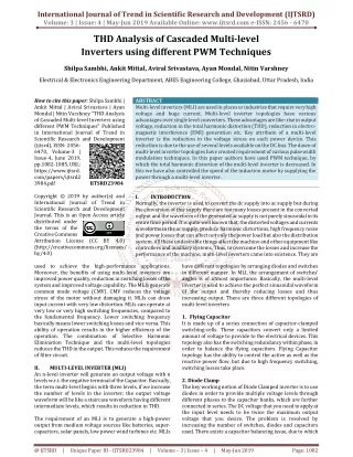
International Journal of Trend in Scientific Research and Development (IJTSRD) Volume: 3 | Issue: 4 | May-Jun 2019 Available Online: www.ijtsrd.com e-ISSN: 2456 - 6470 THD Analysis of Cascaded Multi-level Inverters using different PWM Techniques Shilpa Sambhi, Ankit Mittal, Aviral Srivastava, Ayan Mondal, Nitin Varshney Electrical & Electronics Engineering Department, ABES Engineering College, Ghaziabad, Uttar Pradesh, India How to cite this paper: Shilpa Sambhi | Ankit Mittal | Aviral Srivastava | Ayan Mondal | Nitin Varshney "THD Analysis of Cascaded Multi-level Inverters using different PWM Techniques" Published in International Journal of Trend in Scientific Research and Development (ijtsrd), ISSN: 2456- 6470, Volume-3 | Issue-4, June 2019, pp.1082-1085, URL: https://www.ijtsrd. com/papers/ijtsrd2 3984.pdf Copyright © 2019 by author(s) and International Journal of Trend in Scientific Research and Development Journal. This is an Open Access article distributed under the terms of the Creative Commons Attribution License (CC BY 4.0) (http://creativecommons.org/licenses/ by/4.0) used to achieve the high-performance applications. Moreover, the benefits of using multi-level inverters are improved power quality, reduction in switching losses of the system and improved voltage capability. The MLIs generate common mode voltage (CMV). CMV reduces the voltage stress of the motor without damaging it. MLIs can draw input current with very low distortion. MLIs can operate at very low or very high switching frequencies, compared to the fundamental frequency. Lower switching frequency basically means lower switching losses and vice versa. This ability of operation results in the higher efficiency of the operation. The combination of Selective Harmonic Elimination Technique and the multi-level topologies reduces the THD in the output. This reduces the requirement of filter circuit. II. MULTI-LEVEL INVERTER (MLI) An n-level inverter will generate an output voltage with n levels w.r.t. the negative terminal of the Capacitor. Basically, the term multi-level begins with three levels, if we increase the number of levels in the inverter; the output voltage waveform will be like a staircase waveform having different intermediate levels, which results in reduction in THD. The requirement of an MLI is to generate a high-power output from medium voltage sources like batteries, super- capacitors, solar panels, low power wind turbines etc. MLIs ABSTRACT Multi-level inverters (MLI) are used in places or industries that require very high voltage and huge current. Multi-level inverter topologies have various advantages over single level converters. These advantages are like: rise in output voltage, reduction in the total harmonic distortion (THD), reduction in electro- magnetic interference (EMI) generation etc. Key attribute of a multi-level inverter is the reduction in the voltage stress on each power device. This reduction is due to the use of several levels available on the DC bus. The dawn of multi-level inverter topologies have created requirement of various pulse width modulation techniques. In this paper authors have used PWM technique, by which the total harmonic distortion of the multi-level inverter is decreased. In this we have also controlled the speed of the induction motor by supplying the power through a multi-level inverter. I. INTRODUCTION Normally, the inverter is used to convert the dc supply into ac supply but during the conversion of this supply there are too many losses present in the converted output and the waveform of the generated ac supply is not purely sinusoidal in its entire time period. It is quite well known that, the distorted voltages and currents waveforms in the ac supply, produce harmonic distortions, high frequency noise and power losses that can affect not only the power load but also the distribution system. All these undesirable things affect the machine and other equipment like controllers and auxiliary systems. Thus, to overcome the losses and increase the performance of the machine, multi-level inverters came into existence. They are IJTSRD23984 have different topologies by arranging diodes and switches in different manner. In MLI, the arrangement of switches’ angles is of utmost importance. Basically, the multi-level inverter is used to achieve the perfect sinusoidal waveform of the output and thereby reducing losses and thus increasing output. There are three different topologies of multi-level inverters 1. Flying Capacitor It is made up of a series connection of capacitor-clamped switching-cells. These capacitors convert only a limited amount of voltage to provide to the electrical devices. This topology also has the switching redundancy within phase, in order to balance the flying capacitors. Flying Capacitor topology has the ability to control the active as well as the reactive power flow, but due to high frequency switching, switching losses take place. 2. Diode Clamp The key working notion of Diode Clamped inverter is to use diodes in order to provide multiple voltage levels through different phases to the capacitor banks, which are further connected in series. The DC voltage that you need to apply at the input level needs to be twice the maximum output voltage that you desire. The problem is resolved by increasing the number of switches, diodes and capacitors used. There exists a capacitor balancing issue, due to which @ IJTSRD | Unique Paper ID - IJTSRD23984 | Volume – 3 | Issue – 4 | May-Jun 2019 Page: 1082
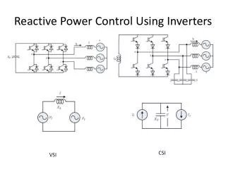
International Journal of Trend in Scientific Research and Development (IJTSRD) @ www.ijtsrd.com eISSN: 2456-6470 these are limited only to three level multi-level inverters. Diode Clamp MLI provides improved performance and efficiency due to the use of fundamental frequency for all the switching devices. Moreover, it is a simple method for back to back power transfer systems. 3. Cascaded H-Bridge(CHB) The Cascaded H-bridge MLI uses capacitors and switches. The power can be easily scaled, since it is composed of a series of power conversion cells and thus the power can be easily scaled. This combination of capacitors and switches’ pair is called an H-bridge and gives a separate input DC voltage for each H-bridge. This model has H-bridge cells, and each cell can provide the load with three different voltages, like zero, +ve DC and -ve DC voltages. As the levels increase, the control complexity increases and voltage imbalance problems are observed. There are several modulations and controlling techniques that have been developed for MLIs, out of which some of them are Multi- level Sinusoidal Pulse Width Modulation (SPWM) Multi-level Selective Harmonic Elimination, Modulation (SVM). The main features due to which we used this type of multi-level inverter in our project are: 1.The output voltage of multi-level inverters is of low distortion with reduced dv/dt. 2.The input current that is drawn has reduced distortion. 3.the CMV generated is small. This helps in the reduction of the stress in the motor bearings. In addition to all this, using sophisticated modulation methods we can eliminate CMV. 4.Cascaded H-Bridge MLI can operate with reduced switching frequency. But apart from having large number of advantages multi-level inverter have some disadvantages and that are: - The number of components used is high. The Cascaded H- Bridge inverter uses a large number of MOSFET modules. The 5-level CHB MLI needs about 24 MOSFETS, with all the gate drivers having the same number. The CHB MLI requires a large number of isolated dc supplies to run. A stiff DC supply, using an expensive phase shifting transformer, is usually used to provide the various DC supplies for the CHB inverter. III. SINGLE-PHASE 5-LEVEL INVERTER The cascaded inverter shown in the figure has five voltage levels. The output voltage that will be obtained can be 0, ±E, ±2E. It is observed that different voltage levels can obtain when two or more switches are in switching state. This MLI provides huge pliability for switching pattern design, mainly for SVM schemes. Generally, if N is the number of single- phase H-bridges per phase, the total number of levels of the inverter is: m= (2N+1) where, N is the number of H-bridge cells per phase leg and for CHB inverter the value of m should be odd. The Cascade H-Bridge MLI showed above, can be extended to any number of voltage levels. Let Ns be the total number of active switches (IGBTs, MOSFETs) used in the CHB inverters can be determined by, Ns = 6(m – 1) where, Ns = the total number of switches used m= the voltage level. Fig 1: 1-phase 5-level CHB Inverter In this diagram, total 8 MOSFETS are used and, it gives us the output of 5-level voltage. The output is then provided to a resistive load. Comparison of the triangular wave and the sinusoidal wave generates the pulses. For 5-level output, (n- 1) triangular waves are taken. This means that 4 triangular waveforms are required, which are compared to the sinusoidal waveform and thus each MOSFET is given a pulse with necessary time gap. and Space-Vector CHB MULTI-LEVEL Fig 2: 1-phase 5-level CHB Inverter IV. LEVEL INVERTER The per-phase diagram of seven-level inverter is depicted in Figure 2, where seven-level inverter has three H-bridge cells in cascade as shown in the figure. The 7-level CHB Multi Level Inverter has improved efficiency and better THD handling. It has reduced Harmonic Distortion than five-level MLI. This model is by far the best model which we made. It gave the best simulation results and least THD in the output. V. LEVEL SHIFTED MODULATION SCHEME: Multiple carrier pulse modulation A number of carriers are used in multi-level SPWM. For ‘n’ level inverter ‘n-1’ carriers are used. These are following three types SINGLE-PHASE 7-LEVEL CHB MULTI- @ IJTSRD | Unique Paper ID - IJTSRD23984 | Volume – 3 | Issue – 4 | May-Jun 2019 Page: 1083
International Journal of Trend in Scientific Research and Development (IJTSRD) @ www.ijtsrd.com eISSN: 2456-6470 1.IN- PHASE DIPOSITION (IPD) In this all the carries are in phase with respect to each other. Fig 3: PD-PWM 2. PHASE OPPOSITIONDISPOSITION (POD) In POD technique, the carrier waveforms that are above the zero are all out of phase with those below the zero by 180º. Fig 7: Image of the output waveform of a 7-level multi- level inverter with APOD Fig 4: POD-PWM 3. ALTERNATE DISPOSITION(APOD) APOD technique needs every (x – 1) carrier waveform, for an x-level phase waveform, to be displaced by phase from each other by 180º alternately PHASE OPPOSITION Fig 8: The First Fourier Transform Analysis of 5-level multi-level inverter with Alternate Phase Opposition Disposition Fig 5: APOD-PWM From all the above technique, APOD TECHNIQUE has the least THD. So, the above simulations are done by using APOD technique. VI. SIMULATION RESULTS In this section we will be showing the simulation result of both the simulations. The output we get at the load side and the FFT analysis of both the simulation when we used APOD technique. Fig 9: Image of the output waveform of a 5-level multi- level inverter with Alternate Phase Opposition Disposition V. CONCLUSION The Simulation results shows the performance and effectiveness of 1-Ф 5-level cascaded H-bridge multi-level inverter and 7-level cascaded H-bridge multi-level inverter of the proposed circuit for R-load, the result obtained is having 5-level and 7-level of voltage and current .form by using all the three PWM techniques like as:-IPD,POD,APOD. After the comparison of the THD values obtained from all the techniques we have concluded that APOD is much better than other two techniques for the practical approach. REFERENCE [1]J. Rodriguez, J. S. Lai, F. Zheng. “Multi-level Inverters: A survey of Topologies, controls, and applications” IEEE Transactions on Industrial electronic, Vol 49. No 4. August 2002. pp 724-738. [2]P. Palanivel S. S. Dash, "Analysis of THD and output voltage performance for cascaded multi-level inverter using carrier pulse width modulation technique," iET Power Electron., vol. 4, Iss. 8, pp. 951-958, 201 l. Fig 6: The First Fourier Transform Analysis of 7-level multi-level inverter with APOD @ IJTSRD | Unique Paper ID - IJTSRD23984 | Volume – 3 | Issue – 4 | May-Jun 2019 Page: 1084
International Journal of Trend in Scientific Research and Development (IJTSRD) @ www.ijtsrd.com eISSN: 2456-6470 [3]B. P. McGrath, D. G. Holmes, "MulticalTier PWM strategies for multi-level invelters," IEEE Trans. Ind. Electronics., vol. 49, no. 4, pp.858-867, August 2002. Power Electronics, Vol. 17 N°1, January 2002, pp.125- 131 [7]Tolber, L.M., Habetler, T. G.: ‘Novel multi-level inverter carrier based PWM method’, IEEE Ind. Appl., 1999, 35, pp. 1098–11079. [4]E. Babaei, S. Alilu , S. L. A Karnik, "A New General Topology for Cascaded Multi-level Invelters With Reduced Number of Components Based on Developed H-Bridge," iEEE Trans. on industrial Electronics, vol.61 , no. 8, pp. 3932-3939, October, 2013 [8]Naderi, R., Rahmati, A.: ‘Phase-shifted carrier PWM technique forgeneral cascaded inverters’, IEEE Trans. Power Electron., 2008, 23, pp. 1257–1269 Fig. 10 Phase-shifted pulse-width modulation output voltage a SH PWM b SFO PWM 958. [5]E. Babaei, "A cascade multi-level converter topology with reduced number of switches," iEEE Trans. Power Electron, vol. 23, no. 6, pp. 2657-2664, November 2008 [9]International Journal of Innovative Research in Advanced Engineering (IJIRAE) ISSN: 2349-2163 Volume 1 Issue 12 (December 2014) [6]Keith Corzine, and Yakov Familiant, “A New Cascaded Multi-level H-Bridge Drive”, IEEE Transactions on @ IJTSRD | Unique Paper ID - IJTSRD23984 | Volume – 3 | Issue – 4 | May-Jun 2019 Page: 1085