Download
1 / 7
80 likes | 178 Views
Nowadays, remote manipulation of a climbing robot by a human operator becomes essential for hazard environment. Carrying objects on stable platform is useful as a popular application. This paper presents the design and implementation of a remote controlled stair climbing robot with stable platform. The robot movement is controlled using Arduino UNO and Android Bluetooth connection. The paper presents a complete integrated control design and communication strategy for Bluetooth range. Moreover self balanced stable platform is designed using MPU6050 IMU sensor. Its mechanical design using DC geared wheels and servo based arm is designed for climbing stairs. The robot system is implemented by using Arduino IDE and MIT App Inventor for android application is developed for remote access. Experimental tests showed that stair climbing process and stable platform were successful integrated and they can be directly applied for various types of stairs and carrying light weighted cap or goods. Moh Moh Myint Maung | Soe Nay Lynn Aung "Stair Climbing Robot with Stable Platform" Published in International Journal of Trend in Scientific Research and Development (ijtsrd), ISSN: 2456-6470, Volume-3 | Issue-4 , June 2019, URL: https://www.ijtsrd.com/papers/ijtsrd25221.pdf Paper URL: https://www.ijtsrd.com/engineering/electronics-and-communication-engineering/25221/stair-climbing-robot-with-stable-platform/moh-moh-myint-maung<br>

E N D
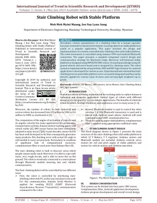
International Journal of Trend in Scientific Research and Development (IJTSRD) Volume: 3 | Issue: 4 | May-Jun 2019 Available Online: www.ijtsrd.com e-ISSN: 2456 - 6470 Stair Climbing Robot with Stable Platform Moh Moh Myint Maung, Soe Nay Lynn Aung Department of Electronics Engineering, Mandalay Technological University, Mandalay, Myanmar How to cite this paper: Moh Moh Myint Maung | Soe Nay Lynn Aung "Stair Climbing Robot with Stable Platform" Published in International Journal of Trend in Scientific Research and Development (ijtsrd), ISSN: 2456- 6470, Volume-3 | Issue-4, June 2019, pp.1674-1680, URL: https://www.ijtsrd.c om/papers/ijtsrd25 221.pdf Copyright © 2019 by author(s) and International Journal of Trend in Scientific Research and Development Journal. This is an Open Access article distributed under the terms of the Creative Commons Attribution License (CC BY 4.0) (http://creativecommons.org/licenses/ by/4.0) Moreover, the number of robots, in both industrial and service robots, has increased from 4.5 million in 2006 to 8.6 million in 2008, as mentioned in [5]. ABSTRACT Nowadays, remote manipulation of a climbing robot by a human operator becomes essential for hazard environment. Carrying objects on stable platform is useful as a popular application. This paper presents the design and implementation of a remote controlled stair-climbing robot with stable platform. The robot movement is controlled using Arduino UNO and Android Bluetooth connection. The paper presents a complete integrated control design and communication strategy for Bluetooth range. Moreover self-balanced stable platform is designed using MPU6050 IMU sensor. Its mechanical design using DC geared wheels and servo based arm is designed for climbing stairs. The robot system is implemented by using Arduino IDE and MIT App Inventor for android application is developed for remote access. Experimental tests showed that stair climbing process and stable platform were successful integrated and they can be directly applied for various types of stairs and carrying light weighted cap or goods. Keywords: Arduino, DC Motors, IMU sensors, Servo Motors, Stair Climbing Robot, MIT App Inventor I. INTRODUCTION Nowadays robots are being implemented for working tasks to replace human in industrial and domestic application. Several types of robots with different designed are designed for various robotic applications. The benefits of robots for urban disasters, hostage situations, and explosions cover in many areas [1-4]. IJTSRD25221 ?Second, Bluetooth module is used to control the robot wireless. 2.4 GHz Bluetooth transceiver is used and is paired with Android smart phone. Android will send command using UART communication too. ?Third, for stabling upper sided platform, complementary filter is applied using appropriate coefficient value. The computation of the angles of inclination of a device and its angular velocity has many applications for aeronautics, transportation systems, human motion tracking, games and virtual reality [6]. IMU sensor fusion has been extensively adopted in many areas [7][8]. In past decades, sensor fusion has been well developed so far that consequently generates many products. But checking error with actual tilt angle is still needed to carry out precisely. Particularly in condition of significant lack of complementary filter is used more than Kalman filter [9]. II. The block diagram shown in Figure 1 presents the main structure of the stair-climbing robot with stable platform in which 12 V Battery, 5 V regulator, Arduino, motors and Bluetooth module are included. Arduino controls servo motors for roll and pitch angles of stable platform and motors for vehicle motion and climbing operation. STAIRCLIMBING ROBOT DESIGN computational resources, The stair climbing robot is built to discover areas which people cannot easily reach. Moreover, it is able to cope with stairs, very rough terrain, and is able to move fast on flat ground. The robot is wirelessly connected to a smart phone through Bluetooth module ensuring fast and reliable communication. The Stair-climbing Robot will be controlled by two different ways: ?First, the robot is controlled by interfacing stair- climbing robot with PC; in this way serial port was used. For this communication, Arduino Serial Monitor is applied for sending RS232 (UART (Universal Asynchronous Receiver Transmitter) communication command to the robot. Figure1. The Block Diagram of the System DESIGN CONSIDERATION This system can be divided into four parts: IMU sensor, Complementary filter, Android application development, Arduino program development and overall circuit design. III. @ IJTSRD | Unique Paper ID – IJTSRD25221 | Volume – 3 | Issue – 4 | May-Jun 2019 Page: 1674
International Journal of Trend in Scientific Research and Development (IJTSRD) @ www.ijtsrd.com eISSN: 2456-6470 A.IMU sensor MPU6050 sensor is applied for declination angle sensing. It is a complete 6-axis Motion Tracking Device. It combines 3- axis Gyroscope, 3-axis Accelerometer and Digital Motion Processor all in small package. The ADXL345 is a small, thin, ultralow power, 3-axis accelerometer with high resolution (13-bit) measurement at up to ±16 g. Digital output data is formatted as 16-bit twos complement and is accessible through either a SPI (3- or 4-wire) or I2C digital interface. This is well suited for mobile device applications. It measures the static acceleration of gravity in tilt-sensing applications, as well as dynamic acceleration resulting from motion or shock. Its high resolution (3.9 mg/LSB) enables measurement of inclination changes less than 1.0°. The following equation can give Roll (θ) - Angle of rotation along the X axis Pitch (ψ) - Angle of rotation along the Y axis Yaw (Φ)- Angle of rotation along the Z axis. Figure 2 represents tilt angles of inclined object. Figure3. Complementary filter Representation diagram Complementary Filter coefficient is can be calculated as Where = Time Constant given by cutoff frequency and dt is sampling rate. Functional block diagram is shown in the following Figure 4. At first, program needs to record time in milli-second. And then acceleration and gyroscope rate are recorded. Moreover, the calculation using arctan function for acceleration and recording new milli-second time is preceded consequently. The time interval is calculated by subtracting old milli-second record from new one. For getting changes in one second rate, this time interval is divided by 1000 because gyroscope can give changes in one second only. Multiplying these rate and time interval gives the angle changes. By adding these angle changes to old angle, the inclination angle can be recorded. The complementary filtering will perform using predefined coefficient for low-pass and high-pass operations. After getting inclination angles, old angles are needed to replace with new angle for gyroscope rate calculation for next program sequence. Figure2. Roll, pitch and yaw angles of inclined object The L3G4200D is three-axis angular rate sensor, with a digital I2C/SPI serial interface standard output. The device has a full scale of ±250/±500/ ±2000 Degree per second and is capable of measuring rates with a user-selectable bandwidth. The device may be configured to generate interrupt signals by an independent wake-up event. Gyroscope can detect only angular rate, so the new angle can be get from integrating rate and adding to old angle as follow. GyroAngle(n)=GyroAngle(n-1)+RateGyroAngle (n)*dt where dt = sampling period. B.Complementary Filter Accelerometer gives acceleration with respect to earth reference frame and gyroscope gives angular rate. The output of accelerometer is much nosier than that of gyroscope and gyroscope occurs non-return zero error due to integration. Acceleration can be converted into inclination angles using Euler’s calculation and gyroscope rate can be integrated numerically. Control algorithm of complementary filter is shown in following Figure. 3. Figure4. Flowchart of complementary filter process C.Android Application Development For smart phone application development, MIT App Inventor for Android is chosen. App Inventor for Android is an open- source web application originally provided by Google, and now maintained by the Massachusetts Institute of Technology (MIT). It uses a graphical interface, which allows users to drag-and-drop visual objects to create an application that can run on Android devices. As December 2015, there were 140,000 weekly active users and 4 million registered users in 195 countries, run total of 12 million built applications. In this screen, Bluetooth connection, vehicle movement control and servo arm control are composed for whole application as shown in Figure 5. @ IJTSRD | Unique Paper ID – IJTSRD25221 | Volume – 3 | Issue – 4 | May-Jun 2019 Page: 1675
International Journal of Trend in Scientific Research and Development (IJTSRD) @ www.ijtsrd.com eISSN: 2456-6470 For Bluetooth connection, one list picker is applied to select Bluetooth devices from paired devices list of smart phone using Bluetooth Client Plugin function. The two states of Bluetooth conditions such as connected or not-connected will be expressed on that label. Moreover, one second timer is added for checking Bluetooth connection in every second. Drag-and-drop visual objects for Bluetooth communication are designed as following. Figure7. Visual Program for Picking Paired Bluetooth Device and for Getting Name and Address of Selected Device Figure8. Visual Program for Checking Condition of Selected Bluetooth Device Figure 7 represents the three conditions: 1.checking paired devices before clicking bluetooth listpicker 2.getting name and address of selected device after clicking the listpicker 3.checking selected paired device condition which is still connected or been disconnected. Figure5. Home Screen Design of Application For vehicle movement control, five buttons are applied for ‘Forward’, ‘Backward’, ‘Left’, ‘Right’ and ‘Stop’ commands. For servo arm movement, 90 degree is set as default (release) condition and 135 and 150 degree command are applied for climb up operation. Also, 45 and 30 degree command are applied for climb down operation as shown in Figure 6. Figure9. Visual Program for Sending Command for Vehicle Movement Figure6. Three kinds of controls for Bluetooth, Vehicle and Arm @ IJTSRD | Unique Paper ID – IJTSRD25221 | Volume – 3 | Issue – 4 | May-Jun 2019 Page: 1676
International Journal of Trend in Scientific Research and Development (IJTSRD) @ www.ijtsrd.com eISSN: 2456-6470 For controlling vehicle movement, five types of strings “front”, “back”, “left”, “right” and “stop” are prepared for sending via Bluetooth as shown in Figure9. Figure10. Visual Program for Sending Command for Servo Motor Drive for Fore Arm Movement For controlling for arm movement, five types of strings “150”, “135”, “90”, “45” and “30” are prepared for sending via Bluetooth as shown in Figure 7. D.Arduino Program Development The Arduino integrated development environment (IDE) is a cross-platform application (for Windows, macOS, Linux) that is written in the programming language Java. The Arduino IDE supplies a software library from the wiring project, which provides many common input and output procedures. In this work, 9600 bits per second serial UART communication is applied. Whenever the valid character is received via serial UART, that data is added to the string named “Input”. Then the program will check the length of “Input” string and it will check command for vehicle or servo angle. According to input command, the program will drive vehicle and servo. After that it will clear “Input” as expressed in the flowchart of Figure 11. For stable platform, roll and pitch angle sensing and complementary filter is executed for servo drive. Figure11. Program Flowchart for Arduino UNO E.Overall Circuit Design For driving the vehicle, 12 V 1A geared motor which can rotate up to 20 RPM (as shown in Figure 12) is applied for robot motion. Each robot wheel wides for 2.5 inches diameter and one revolution longs for 7.85 inches. So this robot can travel up to 13 feet per minute. The torque of each motor is 300 G.CM which is acceptable range for light weigh robot. Figure12. 20 RPM Side Shaft Gear DC Motor @ IJTSRD | Unique Paper ID – IJTSRD25221 | Volume – 3 | Issue – 4 | May-Jun 2019 Page: 1677
International Journal of Trend in Scientific Research and Development (IJTSRD) @ www.ijtsrd.com eISSN: 2456-6470 Figure15. Overall Circuit Diagram of the System IV. Firstly, simulation test is performed using Proteus VSM. After writing program using Arduino IDE (Integrated Development Environment) and the HEX file is generated and it is imported to Proteus VSM software. The following Figure 16 shows the simulated design consideration. In this, Bluetooth is connected to USB Serial converter and transmit data is collected COM port directly in Proteus Software. The simulation result is shown in Figure 17. Using Virtual Terminal tool, signal from Bluetooth can be seen clearly. Moreover, servo angle and DC motor directions can be checked which is correct or not. TESTS AND RESULTS Figure13. MG995 Metal Geared Servo Motor For lifting for arm of robot, MG995 metal gear (as shown in Figure 13) servo motor is used. It has 9.4 kg/cm stall torque. So it can handle light weigh for arm easily. It needs 4.8 V to 7.2 V ranges and 1200 mA maximum current draw. Rotational degree is 180 degree and operation speed is 0.2s/60°. For handling 1200 mA and 5V supply range, 5V 3A CA1253 supply card is applied as shown in Figure 14. CA1253 use LM2576 5V 3A regulator IC. Figure16. Simulation Test using Proteus and Android Figure14. CA 1253 Module For driving two DC motors for vehicle, 2A current draw is needed for motor driver. L298N motor controller module is applied for vehicle movement. This motor controller can be used to drive two DC motors at up to 2A each, with a voltage between 5 and 35V DC. The controller has fast short-circuit protection diodes, and a nice heat sink to keep the L298N from overheating. Although there is also an on-board 5V regulator, it is not used in this circuit. Digital pin 9 is attached to servo motor and pin 2, 3, 4 and 5 are feed to L298N input. Arduino serial receive pin is connected to HC06 Bluetooth module. The overall circuit diagram is expressed in Figure 15. Figure17. Simulation Result in Proteus Software Figure 18 shows experimental setup for robot. DC geared motors are equipped at the joint between robot body and fore arm. Using plastic chain, these DC gear motor perform moving and climbing operation. Servo Motor is attached at the centre of robot and it is used for fore arm moving up and @ IJTSRD | Unique Paper ID – IJTSRD25221 | Volume – 3 | Issue – 4 | May-Jun 2019 Page: 1678
International Journal of Trend in Scientific Research and Development (IJTSRD) @ www.ijtsrd.com eISSN: 2456-6470 down operation. Rechargeable 12V 3000 mA battery is used. It can drive robots for at least 1 hours because two DC motors and one servo motor can take 3A maximum at the same time. Figure18. Constructed Stair climbing Robot Using Bluetooth connection, experimental test is performed as shown in Figure 19 (a). Stable platform is equipped over vehicle as shown in Figure 19 (b). For climbing down operation, servo arm is needed to be downward direction such as 45 degree or 30 degree of servo motor. Figure 20 shows climbing down condition of Robot. Figure20. Robot that climbing down stairs V. In this work, a method of controlling a stair climbing robot is proposed. The hardware system based on Arduino UNO is designed, and then developed Android application using MIT App Inventor. Basic operations such as moving in any direction, climbing up and down are tested successfully. As the length of robot body is 1.2 feet and fore arm long for 1 foot, the riser of stair must be shorter than 1 foot and thread of stair should be longer than 1.2 feet. The system which is proposed can ascend and descend the stairs. Moreover, it can be moved on the floor as a general robot. Its payload is about 1 kg. It is actually an evolutionary thing which makes travel through stairs. By adding camera and range sensor, it can be easily be transformed autonomous inquiry robot. ACKNOWLEDGMENT The author would like to thank all the teachers from the Department of Electronics Technological University (M.T.U). And I also would like to thank supervisor Soe Nay Lynn Aung, my family and my friends who have helped me during this research. And also, thank for Dr. Tin Tin Hla, Head of the department. REFERENCES [1]H. Utz, S. Sablatnog, S. Enderle, G. Kraetzschmar, “Miro– Middleware for mobile robot applications”, IEEE Transactions on Robotics and Automation, vol.18, 2002, pp. 493- 497. CONCLUSIONS AND DISCUSSION (a) Engineering, Mandalay [2]Akhtaruzzaman, M.; IzzatiBt Samsuddin, N.; Bt Umar, N.; Rahman, M.;” Design and development of a wall climbing Robot and its control system” 12th International Conference Information Technology, 2009. ICCIT '09. on Computers and [3]Sung Kyun Lim Dong Il Park Yoon Keun Kwak Byung- Soo Kim Sang-Won Jeon, “ Variable geometry single- tracked mechanism for a rescue robot” , Workshop, 2005 IEEE International Safety, Securityand Rescue Robotics. (b) Figure19. Controlling Robot via (a) Android Smart Phone (b) PC @ IJTSRD | Unique Paper ID – IJTSRD25221 | Volume – 3 | Issue – 4 | May-Jun 2019 Page: 1679
International Journal of Trend in Scientific Research and Development (IJTSRD) @ www.ijtsrd.com eISSN: 2456-6470 [4]Gaston, J. Raahemifar, K. Hiscocks, P “ A cooperative network of reconfigurable stair-climbing robots”, ISCAS 2006. Proceedings. Symposium on Circuits and Systems, 2006. [7]B. Delporte, L. Perroton, T. Grandpierre, J. Trichet, “Accelerometer and Magnetometer Based Gyroscope Emulation on Smart Sensor for a Virtual Reality Application”, Sensor and Transducers Journal, 2012 IEEE International [5]E. Guizzo, "World Robot Population Reaches 8.6 Million", IEEE Spectrum: Technology, Engineering, and Science News, 2010. [Online]. Available: https:// spectrum.ieee.org/automaton/robotics/ industrial- robots/041410-world-robot-population. [Accessed: 02- Dec- 2017]. [8]S. Popowski, “Determining pitch and roll in inexpensive land navigation systems,” Journal Aeronautica Integra, vol. 1, pp. 93–97, 2008 [9]A. Cavallo, A. Cirillo, P. Cirillo, G. De Maria, P. Falco, C. Natale, S. Pirozzi, “Experimental Comparison of Sensor Fusion Algorithms for International Federation of Automatic Control Cape Town, August 24-29, 2014 Attitude Estimation”, [6]S. O. H. Madgwick and A. J. L. Harrison, “Estimation of IMU and MARG orientation using a gradient descent algorithm”, IEEE International Conference on Rehabilitation Robotics Rehab WeekZurich, ETH Zurich Science City, Switzerland, (2011) June 29 - July 1, 2011 @ IJTSRD | Unique Paper ID – IJTSRD25221 | Volume – 3 | Issue – 4 | May-Jun 2019 Page: 1680