Download
1 / 7
70 likes | 94 Views
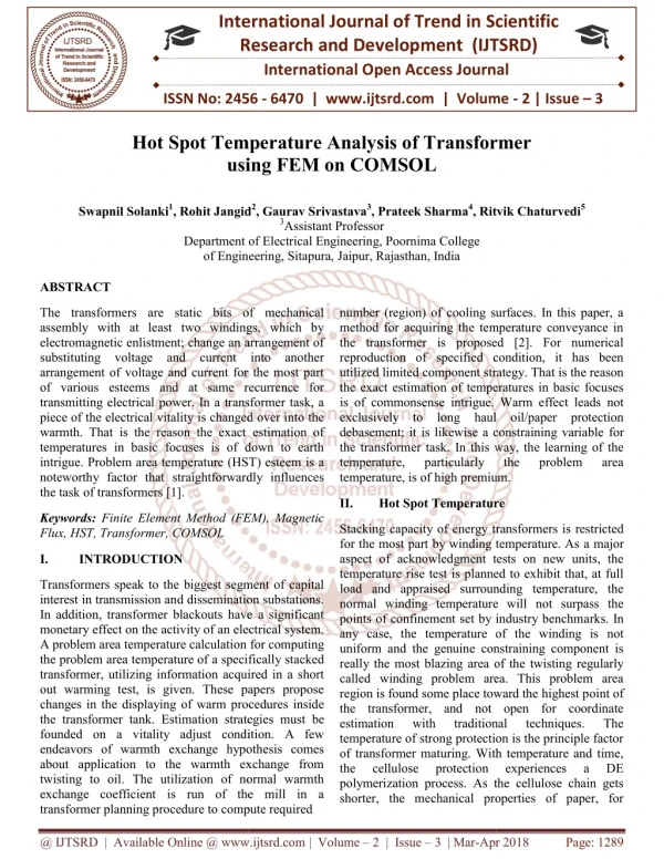
The transformers are static bits of mechanical assembly with at least two windings, which by electromagnetic enlistment change an arrangement of substituting voltage and current into another arrangement of voltage and current for the most part of various esteems and at same recurrence for transmitting electrical power. In a transformer task, a piece of the electrical vitality is changed over into the warmth. That is the reason the exact estimation of temperatures in basic focuses is of down to earth intrigue. Problem area temperature HST esteem is a noteworthy factor that straightforwardly influences the task of transformers 1 . Swapnil Solanki | Rohit Jangid | Gaurav Srivastava | Prateek Sharma | Ritvik Chaturvedi "Hot Spot Temperature Analysis of Transformer using FEM on COMSOL" Published in International Journal of Trend in Scientific Research and Development (ijtsrd), ISSN: 2456-6470, Volume-2 | Issue-3 , April 2018, URL: https://www.ijtsrd.com/papers/ijtsrd11280.pdf Paper URL: http://www.ijtsrd.com/engineering/electrical-engineering/11280/hot-spot-temperature-analysis-of-transformer-using-fem-on-comsol/swapnil-solanki<br>

E N D
International Research Research and Development (IJTSRD) International Open Access Journal Hot Spot Temperature Analysis of Transformer using FEM on COMSOL International Journal of Trend in Scientific Scientific (IJTSRD) International Open Access Journal ISSN No: 2456 ISSN No: 2456 - 6470 | www.ijtsrd.com | Volume 6470 | www.ijtsrd.com | Volume - 2 | Issue – 3 Hot Spot Temperature Analysis of Transformer using FEM on COMSOL Hot Spot Temperature Analysis of Transformer Swapnil Solanki1, Rohit Jangid , Rohit Jangid2, Gaurav Srivastava3, Prateek Sharma4, Ritvik Chaturvedi 3Assistant Professor Department of Electrical Engineering, Poornima College , Ritvik Chaturvedi5 Department of Electrical Engineering, Poornima College of Engineering, Sitapura, Jaipur, Rajasthan, India of Engineering, Sitapura, Jaipur, Rajasthan, India ABSTRACT The transformers are static bits of mechanical assembly with at least two windings, which by electromagnetic enlistment; change an arrangement of substituting voltage and current into another arrangement of voltage and current for the most part of various esteems and at same recurrence for transmitting electrical power. In a transformer task, a piece of the electrical vitality is changed over into the warmth. That is the reason the exact estimation of temperatures in basic focuses is of down to earth intrigue. Problem area temperature (HST) esteem is a noteworthy factor that straightforwardly influences the task of transformers [1]. The transformers are static bits of mechanical assembly with at least two windings, which by electromagnetic enlistment; change an arrangement of substituting voltage and current into another arrangement of voltage and current for the most part esteems and at same recurrence for transmitting electrical power. In a transformer task, a piece of the electrical vitality is changed over into the warmth. That is the reason the exact estimation of temperatures in basic focuses is of down to earth ue. Problem area temperature (HST) esteem is a noteworthy factor that straightforwardly influences number (region) of cooling surfaces. In this paper, a method for acquiring the temperature conveyance in the transformer is proposed [2]. For numerical reproduction of specified condition, it has been utilized limited component strategy. That is the reason the exact estimation of temperatures in basic focuses is of commonsense intrigue. Warm effect leads not exclusively to long haul oil/paper protection debasement; it is likewise a constraining variable for the transformer task. In this way, the learning of the temperature, particularly number (region) of cooling surfaces. In this paper, a method for acquiring the temperature conveyance in the transformer is proposed [2]. For numerical reproduction of specified condition, it has been utilized limited component strategy. That is the reason the exact estimation of temperatures in basic focuses is of commonsense intrigue. Warm effect leads not exclusively to long haul oil/paper protection debasement; it is likewise a constraining variable the transformer task. In this way, the learning of the temperature, particularly temperature, is of high premium. temperature, is of high premium. the the problem problem area area II. Hot Spot Temperature Hot Spot Temperature Keywords: Finite Element Method (FEM), Magnetic Flux, HST, Transformer, COMSOL Finite Element Method (FEM), Magnetic Stacking capacity of energy transformers is restricted for the most part by winding temperature. As aspect of acknowledgment tests on new units, the temperature rise test is planned to exhibit that, at full load and appraised surrounding temperature, the normal winding temperature will not surpass the points of confinement set by industry benchm any case, the temperature of the winding is not uniform and the genuine constraining component is really the most blazing area of the twisting regularly called winding problem area. This problem area region is found some place toward the highest p the transformer, and not open for coordinate estimation with traditional temperature of strong protection is the principle factor of transformer maturing. With temperature and time, the cellulose protection polymerization process. As the cellulose chain gets shorter, the mechanical properties of paper, for shorter, the mechanical properties of paper, for Stacking capacity of energy transformers is restricted for the most part by winding temperature. As a major aspect of acknowledgment tests on new units, the temperature rise test is planned to exhibit that, at full load and appraised surrounding temperature, the normal winding temperature will not surpass the points of confinement set by industry benchmarks. In any case, the temperature of the winding is not uniform and the genuine constraining component is really the most blazing area of the twisting regularly called winding problem area. This problem area region is found some place toward the highest point of the transformer, and not open for coordinate estimation with traditional temperature of strong protection is the principle factor of transformer maturing. With temperature and time, the cellulose protection zation process. As the cellulose chain gets I. INTRODUCTION Transformers speak to the biggest segment of capital interest in transmission and dissemination substations. In addition, transformer blackouts have a significant monetary effect on the activity of an electrical system. A problem area temperature calculation for computing the problem area temperature of a specifically stacked transformer, utilizing information acquired in a short out warming test, is given. These papers propose changes in the displaying of warm procedures inside the transformer tank. Estimation strategies must be founded on a vitality adjust condition. A few endeavors of warmth exchange hypothesis comes about application to the warmth exchange from twisting to oil. The utilization of normal warmth exchange coefficient is run of the mill in a transformer planning procedure to compute required transformer planning procedure to compute required Transformers speak to the biggest segment of capital interest in transmission and dissemination substations. In addition, transformer blackouts have a significant monetary effect on the activity of an electrical system. on for computing the problem area temperature of a specifically stacked transformer, utilizing information acquired in a short out warming test, is given. These papers propose changes in the displaying of warm procedures inside tion strategies must be techniques. techniques. The The founded on a vitality adjust condition. A few endeavors of warmth exchange hypothesis comes about application to the warmth exchange from twisting to oil. The utilization of normal warmth exchange coefficient is run of the mill in a experiences experiences a a DE DE @ IJTSRD | Available Online @ www.ijtsrd.com @ IJTSRD | Available Online @ www.ijtsrd.com | Volume – 2 | Issue – 3 | Mar-Apr 2018 Apr 2018 Page: 1289
International Journal of Trend in Scientific Research and Development (IJTSRD) ISSN: 2456-6470 example, rigidity and flexibility debase [3]. In the long run the paper winds up weak and isn't fit for withstanding short out powers and even ordinary vibrations that are a piece of transformer life. This circumstance describes the finish of life of the strong protection. Since it is not reversible, it likewise characterizes the transformer end of life. FEM FORMULATION EQUATIONS Coupled field limited component strategy is a numerical methodology for getting limit estimations of scientific model for our situation that would be a transformer show. The standard of the technique is to supplant a constant area by number of sub areas, which are normally alluded to as components whose conduct is displayed by addition work containing a couple of obscure esteems at the hubs of the component. The variable esteems and states of transformers have taken as the spaces of the model. In assessing numerical model, these following advances are critical. This procedure is outstanding to transformer proprietors and supported endeavors have been made to screen the problem area temperature to exploit cool encompassing temperature, broaden the transformer life while giving crisis over-burdening abilities and exploiting market openings. The appraised problem area temperature is 110°C. 1) Discretization of the space It has seen that an expansion of 7°C will twofold the maturing speeding up factor. For more seasoned transformer, the evaluated problem area temperature is either 95°C or 97°C. It is additionally extremely touchy to temperature and if there should arise an occurrence of crisis (accepting a problem area temperature of 140°C); the maturing speeding up factor is around 100, which implies one hour in this condition is identical to 100 hours at the appraised temperature. 2) Induction of the component conditions 3) Gathering of the components 4) Arrangement of the arrangement of conditions The way in which the area is discretized will influence the PC stockpiling necessity, the preparing time, and additionally exactness of the numerical outcomes. High request capacities, albeit more exact, yet in addition more entangled plan. Thus, a straightforward and fundamental direct insertion is still generally utilized. It is noticed that the customary problem area temperature computation technique utilizes various suppositions that are not right: The articulation for the obscure arrangement in a component, say component e, in the accompanying structure ∅le = ∑ (j=1, n) ?je∅je Where n is number of hubs in the component, ∅?e the field an incentive at hub j and the extension work which is otherwise called fundamental capacity or shape work. A first acknowledgment of a transient 3D FE transformer demonstrate utilizing COMSOL Multiphysics 5.3a, generous model advances, most eminently in the usage of non-straight attractive materials, the thought of whirlpool streams and the fuse of a warm model. The electromagnetic FE demonstrate registers the associations between the electrical subsystem on the essential and auxiliary sides and the attractive subsystem. Ampère's circuital law and Faraday's law of enlistment depict them. Oil temperature in the cooling pipe is expected the same as the best oil temperature. The adjustment in twisting protection with temperature is dismissed. The adjustment in temperature is disregarded. The impact of tap position is dismissed. The variety of encompassing temperature is accepted to immediaty affect oil temperature [4]. III. Finite Element Method oil consistency with This problem area territory is found some place toward the highest point of the transformer, and not available for coordinate estimation with traditional strategies considering the impact of relocation current T − Ω technique is received to computing the stray misfortunes in metal auxiliary parts of influence transformer. The summed up arrangement of non-homogeneous warmth conduction condition with non-homogeneous limit condition, in Cartesian facilitate framework is composed in this manner: E = σ + ε (∂ −1)/∂? (∇.?) The above equation is in eddy domains @ IJTSRD | Available Online @ www.ijtsrd.com | Volume – 2 | Issue – 3 | Mar-Apr 2018 Page: 1290
International Journal of Trend in Scientific Research and Development (IJTSRD) ISSN: International Journal of Trend in Scientific Research and Development (IJTSRD) ISSN: International Journal of Trend in Scientific Research and Development (IJTSRD) ISSN: 2456-6470 (10) (1) Largely, warm conductivities are demonstrated extraordinary, and are shown in like manner. Nevertheless, in a genuine case, the warm conductivities in outspread ways (k1 and k2) are equivalent and conductivities pivotal way will likewise be the same (k3 andk4). Warm conductivity has been dealt with as a vector amount, having segments in both outspread and pivotal course. segments in both outspread and pivotal course. Largely, warm conductivities are demonstrated extraordinary, and are shown in like manner. Nevertheless, in a genuine case, the warm conductivities in outspread ways (k1 and k2) are equivalent and conductivities pivotal way will In the district a<x<b and zero<y<l. At the internal tube shaped surface: In the district a<x<b and zero<y<l. At the internal (2) dk4). Warm conductivity At the external tube shaped surface: has been dealt with as a vector amount, having (3) Resultant warm conductivity of the framework can be Resultant warm conductivity of the framework can be evaluated as: At the base level surface: (4) (11) At the best level surface: Where: (5) Conditions (1) through (5) speak to the general warmth conduction condition with convection at all four limit surfaces. In the above conditions, temperature T is a component of room factors x and y. The term Q is the warmth source work and has been adjusted here to deal with variety of resistivity of copper with temperature. The warmth source term Q can be of the frame: Conditions (1) through (5) speak to the general warmth conduction condition with convection at all four limit surfaces. In the above conditions, (12) (13) factors x and y. The term Q is the warmth source work and has been adjusted here to deal with variety of resistivity of copper with temperature. The warmth source term Q Term K speaks to resultant warm conductivity of protection and conductor framework. Warmth exchange coefficients h1 to h4 (htc), are distinctive over all the four surfaces. To decide limit capacities f1 to f4, it is important to compute warm exchange coefficients over the four surfaces. Trouble has been experienced in computation coefficient. It is accounted for somewhere else that it relies upon upwards of 13 factors (e.g., winding size, type, conduit measurements, oil speed, and kind of oil flow, warm transition dispersion, oil warm properties, and so forth.). In this work, amendments have been given for temperature reliance of the warm and physical properties of oil, for example, thickness, particular warmth, volumetric extension and warm conductivity. It was discovered that there is immaterial impact of particular warmth, coefficient of volumetric extension and conductivity in the present Term K speaks to resultant warm conductivity of protection and conductor framework. Warmth exchange coefficients h1 to h4 (htc), are distinctive over all the four surfaces. To decide limit capacities f1 to f4, it is important to compute warm coefficients over the four surfaces. Trouble has been experienced in computation coefficient. It is accounted for somewhere else that it relies upon upwards of 13 factors (e.g., winding size, type, conduit measurements, oil speed, a flow, warm transition dispersion, oil warm properties, and so forth.). In this work, amendments have been given for temperature reliance of the warm and physical properties of oil, for example, thickness, particular warmth, volumetric extens conductivity. It was discovered that there is immaterial impact of particular warmth, coefficient of volumetric extension and conductivity in the present working scope of stacking. (6) warm warm exchange exchange Where, αc is the temperature coefficient of elect protection of copper wire. With this portrayal, the capacity Q progresses toward becoming temperature needy, conveyed warm source. Limit capacities f1(y) and f2(y), got from Newton's law of cooling are of the frame (7) and (8): Where, αc is the temperature coefficient of electrical protection of copper wire. With this portrayal, the capacity Q progresses toward becoming temperature needy, conveyed warm source. Limit capacities f1(y) and f2(y), got from Newton's law of cooling are of the (7) (8) The term Tb is the temperature at the base of the circle or layer, as appropriate. Terms m1 and m2 are the temperature slope along the twisting stature (for layer) or along circle thickness for a plate. Also, capacities f3 and f4representing temperature profiles crosswise over base and best surfaces, having the frame same as appeared in (7) and (8), where temperature angle term has been taken as zero: temperature angle term has been taken as zero: The term Tb is the temperature at the base of the circle or layer, as appropriate. Terms m1 and m2 are the temperature slope along the twisting stature (for layer) or along circle thickness for a plate. Also, capacities f3 and f4representing temperature profiles crosswise over base and best surfaces, having the frame same as appeared in (7) and (8), where Following are a portion of the warmth exchange significant formulae in normal cooling (ON) mode. These formulae have been utilized to ascertain the htc. Nearby Nusselt, number for laminar stream over vertical plates has been demonstrated as Following are a portion of the warmth exchange relations and significant formulae in normal cooling (ON) mode. These formulae have been utilized to ascertain the htc. Nearby Nusselt, number for laminar stream over vertical plates has been demonstrated as follows: (9) (14) @ IJTSRD | Available Online @ www.ijtsrd.com @ IJTSRD | Available Online @ www.ijtsrd.com | Volume – 2 | Issue – 3 | Mar-Apr 2018 Apr 2018 Page: 1291
International Journal of Trend in Scientific Research and Development (IJTSRD) ISSN: International Journal of Trend in Scientific Research and Development (IJTSRD) ISSN: International Journal of Trend in Scientific Research and Development (IJTSRD) ISSN: 2456-6470 Where an and b are the internal and external span of annular circle or layer. Nusselt number of base surface of annular barrel shaped twisting for laminar Where an and b are the internal and external span of annular circle or layer. Nusselt number of b surface of annular barrel shaped twisting for laminar and turbulent administration is in (23): and turbulent administration is in (23): (15) Where Rahf and Grhf are the nearby Rayleigh and Grashof number in light of warmth transition (qw) at trademark measurement (δ). Where Rahf and Grhf are the nearby Rayleigh and Grashof number in light of warmth transition (qw) at (23) Pr is the Prandtl number of transformer oil. Articulation of Rayleigh number in light of consistent warmth transition is: Pr is the Prandtl number of transformer oil. number in light of consistent Utilizing (24) can discover the pivotal oil temperature angle in nearness of cooling by a steady warmth Utilizing (24) can discover the pivotal oil temperature angle in nearness of cooling by a steady warmth motion, because of in this way: motion, because of in this way: (16) (24) Mean Nusselt number for this situation can be figured as: Mean Nusselt number for this situation can be figured Where l is the winding tallness, Dm is the mean width of annular plate or layer of windings. Assurance of limit conditions in constrained convection (OF mode) too requires ascertaining htc. The articulation when the oil speed is bring down qualities, the number in light of temperature distinction is of the type of (25), comparing mean Nusselt number in view of consistent warmth transition is of the type of (26): of consistent warmth transition is of the type of (26): Where l is the winding tallness, Dm is the mean width of annular plate or layer of windings. Assurance of limit conditions in constrained convection (OF mode) too requires ascertaining htc. The articulation when the oil speed is bring down qualities, the mean Nusselt number in light of temperature distinction is of the type of (25), comparing mean Nusselt number in view Notwithstanding, revision to recipe (14) must be given for tube shaped ebb and flow. The amendment factor for this situation is of the structure (30<Pr<50): Notwithstanding, revision to recipe (14) must be given for tube shaped ebb and flow. The amendment accompanying (17) Where: (18) (26) Here Gr is Grashof number in view of temperature contrast. Warmth exchange coefficient can be figured as: Here Gr is Grashof number in view of temperature contrast. Warmth exchange coefficient can be figured (27) Where GzcalledGraetz number. The terms b and w are thickness of oil figured at oil mass mean temperature of oil and at winding divider temperature, individually. Re is the Reynolds number and Pr is the prandtl number. The relative significance of characteristic and constrained cooling is demonstrated by the factor fr=Gr/Re2. On the off chance, that fr 1 then both of the cooling modes must be considered. At a lower estimation of this factor, common cooling can be disregarded. The oil consistency is an imperative property, which relies upon temperature. The equation to take the oil temperature variety into thought is given in (28) underneath from: thought is given in (28) underneath from: Where GzcalledGraetz number. The terms b and w ss of oil figured at oil mass mean temperature of oil and at winding divider temperature, individually. Re is the Reynolds number and Pr is the prandtl number. The relative significance of characteristic and constrained cooling is demonstrated r fr=Gr/Re2. On the off chance, that fr 1 then both of the cooling modes must be considered. At a lower estimation of this factor, common cooling can be disregarded. The oil consistency is an imperative property, which relies upon temperature. to take the oil temperature variety into (19) Where, h speaks to neighborhood coefficient. Mean coefficient (hm) can be figured from mean Nusselt number, as in (15). In the wake of knowing hm for a specific surface, temperature contrast between the winding surface and oil can be discovered, partitioning the hm by the warmth motion through the surface. Mean Nusselt number of best surface of annular barrel shaped twisting for laminar and turbulent administration, will ordinarily be of the frame: Where, h speaks to neighborhood coefficient. Mean figured from mean Nusselt number, as in (15). In the wake of knowing hm for a specific surface, temperature contrast between the winding surface and oil can be discovered, partitioning the hm by the warmth motion through the f best surface of annular barrel shaped twisting for laminar and turbulent administration, will ordinarily be of the (20) (28) (21) Where: (22) (29) (30) @ IJTSRD | Available Online @ www.ijtsrd.com @ IJTSRD | Available Online @ www.ijtsrd.com | Volume – 2 | Issue – 3 | Mar-Apr 2018 Apr 2018 Page: 1292
International Journal of Trend in Scientific Research and Development (IJTSRD) ISSN: International Journal of Trend in Scientific Research and Development (IJTSRD) ISSN: International Journal of Trend in Scientific Research and Development (IJTSRD) ISSN: 2456-6470 The thickness was figured at the mean oil and divider temperature. At first, the winding surface temperature isn't known, so a beginning estimate for winding surface temperature must be made, in the wake of computing the estimation of h, the temperature contrast (Tw-Drudge) is to concur with the expected esteem. To figure winding divider temperature at various surfaces, just base oil temperature is essential. In this paper, the base oil ascend over surrounding temperature has been ascertained as: The thickness was figured at the mean oil and divider winding surface temperature isn't known, so a beginning estimate for winding surface temperature must be made, in the wake of computing the estimation of h, the temperature Drudge) is to concur with the expected a part of the plan procedure and approve the outline parameters. The FEM for the situation examine includes these stages: attractive and warm field a part of the plan procedure and approve the outline parameters. The FEM for the situation examine includes these stages: attractive and warm field dispersion inside the transformer. dispersion inside the transformer. er temperature at various surfaces, just base oil temperature is essential. In this paper, the base oil ascend over surrounding (31) (31) Where u is the base oil temperature, ascend over encompassing Temperature fl is the full load base oil temperature ascend over surrounding temperature acquired from a disconnected test; R is the proportion of load misfortune at appraised load to no misfortune. The variable Iris the proportion of the predefined load to evaluated stack: Where u is the base oil temperature, ascend over the full load base oil temperature ascend over surrounding temperature acquired from a disconnected test; R is the proportion of load misfortune at appraised load to no-heap misfortune. The variable Iris the proportion of the A. Design parameters of the transformer A. Design parameters of the transformer To research the proposed approach, a transformer was composed. Center compose windings are utilized for the theoretical plan. The essential and auxiliary windings have 3E5 layers and each layer 300 turns. The principle parameters of the transformer are To research the proposed approach, a transformer was composed. Center compose windings are utilized for the theoretical plan. The essential and auxiliary windings have 3E5 layers and each layer 300 turns. The principle parameters of the transformer are appeared in table 1. (32) (32) The type n relies on the cooling state. The stacking guide prescribes the utilization of n=0.8 for normal convection and n=0.9-1.0 for constrained cooling. 1.0 for constrained cooling. The type n relies on the cooling state. The stacking guide prescribes the utilization of n=0.8 for normal TABLE I PARAMETERS OF TYPICAL TABLE I PARAMETERS OF TYPICAL TRANSFORMER. TRANSFORMER. Suppositions have been made in the estimation of htc in the channels gave in the plate write windings under oil-constrained (OF) methods of warmth exchange (DOF and NDOF). The cooling in OF mode is because of blended mode (common and constrained) convection. While the oil-stream speed in both vertical and level channels has been accept equivalent, the mode is DOF. In the event that the stream speed in level conduits is expected irrelevant contrasted with speed in the vertical pipes, the mode is NDOF. If there should be an occurrence of DOF mode, the htc was accepted an element of both warmth transition through the surface and the oil stream speed. The system of warmth move in this method of cooling is same in both pivotal and spiral bearing of the plate. If there should arise an occurrence of NDOF mode, the htc in the vertical pipe has been assessed by an indistinguishable recipe from for DOF [5]. Nevertheless, the convection of warmth in the level pipes has been expected aregular compose. Suppositions have been made in the estimation of htc Name Expression Value Value Description plate write windings under Rp 100[ohm] 100 100 Primary side resistance constrained (OF) methods of warmth exchange (DOF and NDOF). The cooling in OF mode is because of blended mode (common and constrained) Rs 100[ohm] 100 100 Secondary side resistance stream speed in both vertical and level channels has been accepted equivalent, the mode is DOF. In the event that the stream speed in level conduits is expected irrelevant contrasted with speed in the vertical pipes, the mode is NDOF. If there should be an occurrence of DOF mode, the htc was accepted an element of both warmth transition through the surface and the oil stream speed. The system of warmth move in this method of cooling is same in both pivotal and spiral bearing of the plate. If there should arise an occurrence of NDOF mode, the htc in the vertical pipe been assessed by an indistinguishable recipe from for DOF [5]. Nevertheless, the convection of warmth in the level pipes has been expected aregular Np 3e5 3E5 3E5 Number of turns in primary winding Ns 300 300 300 Number of turns in secondary winding nu 50[Hz] 50 Hz 50 Hz Frequency of Supply voltage Vac B. Simulations of magnetic field B. Simulations of magnetic field 25[kV] 25000 V 25000 V Supply Voltage In this segment, the reenactment comes about acquired utilizing COMSOL programming [6] [7] is talked about. The shading plotting of the attractive field conveyance for the situation think about got because of the reenactment situation think about got because of the reenactment In this segment, the reenactment comes about acquired utilizing COMSOL programming [6] [7] is talked about. The shading plotting of the attractive field conveyance for the Multiphysics Multiphysics IV. SIMULATION AND RESULTS SIMULATION AND RESULTS The FEM of the transformer is performed to confirm the adequacy of the hypothetical conditions utilized as thetical conditions utilized as The FEM of the transformer is performed to confirm @ IJTSRD | Available Online @ www.ijtsrd.com @ IJTSRD | Available Online @ www.ijtsrd.com | Volume – 2 | Issue – 3 | Mar-Apr 2018 Apr 2018 Page: 1293
International Journal of Trend in Scientific Research and Development (IJTSRD) ISSN: 2456-6470 procedure is clarified. The shading plots of the attractive field conveyance acquired as a result of 2D reproductions is appeared in figure 1. Alluding to the numerical motion thickness esteems appeared in the figure 1, the surface plot of the attractive flux thickness standard conveyance and the bolt plots of the streams in the windings at t = 50 ms. due portrayal for this exclusion and, subsequently, is accepted to give more precise evaluations. Type Stray loss Hot spot factor Hotspot/winding Temperature 69.94oC Without shielding 11Kw 1 48.15oC With shielding 7.5Kw 1.3 A warm model that can screen the warm profile of the transformer has been effectively displayed. A FEM display was adjusted and used to foresee the transformer precise stray misfortunes. The learning of motion thickness was utilized with conductor measurements to foresee the whirlpool misfortunes for a particular outline. The model can be utilized to ascertain the vortex misfortune in singular turns/circles, to find the winding problem area, and to foresee the problem area factor H. Such data is vital for winding problem area assurance. The transition thickness plot of the casing shows that the curl side has extensive motion thickness than that of the tank side, and that the case with a shunt has a littler motion thickness dissemination, when contrasted with the case without. The table demonstrates the aggregate stray misfortunes in transformer without, and with, divider shunts. It can be seen that the decrease of stray misfortunes altogether lessens the misfortunes and problem area temperature productivity and life expectancy of the transformer. The introduced demonstrate permits transient FE examination of transformers, which are coupled to outer hardware. Fig-1: Magnetic flux density norm and the currents in the winding at t = 50ms B.1. Simulation of magnetic flux density norm in the core at t z 50 ms. The shading plots of the warm field appropriation acquired as a result of 2D reproductions is appeared in Fig-2. Magnetic flux density inside the transformer at t = 50ms Figure 2. Attractive flux thickness standard in the center at t z 50 ms. it can be seen that, in figure 2, the extreme estimation of the temperature is 136ºC. and enhance the V. CONCLUSION In this paper, an endeavor has been made to propose a technique to enhance the exactness of forecast of the temperature of the most blazing spot in control transformer by unraveling the warmth exchange fractional differential condition (PDE) numerically. The simply numerical approach for assessing problem area and its area followed in this paper appears to compare sensibly well with the consequences of estimations and real tests and on location estimations. The creators wish to bring up that the IEEE stacking guide and other comparative records offer relations for the estimation of the HST in view of p.u. stack. The plans have a tendency to overlook the potential outcomes of two transformers that are appraising indistinguishable yet have an alternate winding structure and changing warmth misfortune/unit volume. The strategy proposed by the creators gives The transformer is displayed in the mf method of COMSOL Multiphysics 5.3a [8] [9], which settles for the attractive field. The nonlinear polarization normal for the center material is represented in the shape H = f (|B|) eB in light of a worldwide Transformer windings comprising of numerous turns are displayed as mass districts. In the essential conductor, swirl streams are considered by methods for a worldwide condition. Because of their better structure, skin impact can be dismissed in the auxiliary windings. The electromagnetic model likewise processes the time-found the middle value of objective guesswork. @ IJTSRD | Available Online @ www.ijtsrd.com | Volume – 2 | Issue – 3 | Mar-Apr 2018 Page: 1294
International Journal of Trend in Scientific Research and Development (IJTSRD) ISSN: 2456-6470 energy misfortune thickness dissemination, which fills in as a contribution for the warm model. VI. REFERENCES 1.https://en.wikipedia.org/wiki/Transformer 2.http://www.electricenergyonline.com/show_article .php?article=311 3.http://www.ijtra.com/see/estimation area temperature-and-maturing of-a-transformer- .pdf 4.www.ijmer.com/papers/vol%201%20issue%202/ AA012425429.pdf 5.web.mit.edu/kjb/www/Books/FEP_2nd_Edition_4 th_Printing.pdf 6.https://www.comsol.com/comsol-multiphysics 7.https://www.comsol.com/ 8.www.comsol.co.in/display/e-center transformer- 14123 9.https://www.comsol.ru/gathering/string/.../models. acdc.ecore_transformer-20997.pdf of-problem @ IJTSRD | Available Online @ www.ijtsrd.com | Volume – 2 | Issue – 3 | Mar-Apr 2018 Page: 1295