Download
1 / 3
30 likes | 56 Views
In a multi storied building, the beam column joint is one of the most critical regions. Usually the beam column joint was considered as rigid frames. Various researchers over the past years indicated that the joint is not rigid. Now it is also stated that instead of the failure in beam and column, failure can also occur in joint hence joint must be considered as a structural member. The Indian standards define a joint as the portion of the column within the depth of the deepest beam that frames into the column. In framed structures the bending moment and shear forces are maximum at the junction area. So, beam column joint is one of the failure zones. Among the beam column joints, the exterior joint is more critical. The exterior beam column joint have been a study for about 30 years since now. Still there are many more to be understood. In the present work a building is designed in STAAD. Pro V8i and an exterior beam column joint is considered. This joint is modelled in NX CAD and imported to ANSYS to analyse it to derive the shear stress and the corresponding deformation. Pramod Verma | Prof. Pratiksha Malviya "Exterior Beam Column Joint: An Assessment" Published in International Journal of Trend in Scientific Research and Development (ijtsrd), ISSN: 2456-6470, Volume-3 | Issue-2 , February 2019, URL: https://www.ijtsrd.com/papers/ijtsrd21589.pdf Paper URL: https://www.ijtsrd.com/engineering/civil-engineering/21589/exterior-beam-column-joint-an-assessment/pramod-verma<br>

E N D
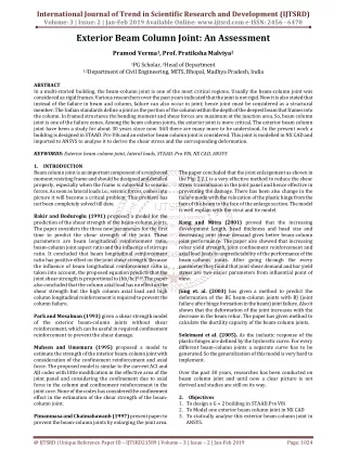
International Journal of Trend in Scientific Research and Development (IJTSRD) Volume: 3 | Issue: 2 | Jan-Feb 2019 Available Online: www.ijtsrd.com e-ISSN: 2456 - 6470 Exterior Beam Column Joint: An Assessment Pramod Verma1, Prof. Pratiksha Malviya2 1PG Scholar, 2Head of Department 1,2Department of Civil Engineering, MITS, Bhopal,Madhya Pradesh, India ABSTRACT In a multi-storied building, the beam-column joint is one of the most critical regions. Usually the beam-column joint was considered as rigid frames. Various researchers over the past years indicated that the joint is not rigid. Now it is also stated that instead of the failure in beam and column, failure can also occur in joint; hence joint must be considered as a structural member. The Indian standards define a joint as the portion of the column within the depth of the deepest beam that frames into the column. In framed structures the bending moment and shear forces are maximum at the junction area. So, beam column joint is one of the failure zones. Among the beam column joints, the exterior joint is more critical. The exterior beam column joint have been a study for about 30 years since now. Still there are many more to be understood. In the present work a building is designed in STAAD. Pro V8i and an exterior beam column joint is considered. This joint is modelled in NX CAD and imported to ANSYS to analyse it to derive the shear stress and the corresponding deformation. KEYWORDS: Exterior beam column joint, lateral loads, STAAD. Pro V8i, NX CAD, ANSYS 1.INTRODUCTION Beam column joint is an important component of a reinforced moment resisting frame and should be designed and detailed properly, especially when the frame is subjected to seismic forces. As soon as lateral loads i.e.; seismic forces, comes into picture it will become a critical problem. This problem has not been completely solved till date. Bakir and Boduroglu (1991) proposed a model for the prediction of the shear strength of thebeam-column joints. The paper considers the three new parameters for the first time to predict the shear strength of the joint. These parameters are beam longitudinal reinforcement ratio, beam-column joint aspect ratio and the influence of stirrups ratio. It concluded that beam longitudinal reinforcement ratio has positive effect on the joint shear strength. Because the influence of beam longitudinal reinforcement ratio is taken into account, the proposed equation predicts that the joint shear strength is proportional to (hb/hc)0.61.The paper also concluded that the column axial load has no effect on the shear strength but the high column axial load and high column longitudinal reinforcement is required to prevent the column failure. Park and Mosalman (1993) given a shear strength model of the exterior beam-column jointswithout shear reinforcement, which can be useful in required confinement reinforcement to prevent the shear damage. Muhsen and Umemura (1995) proposed a model to estimate the strength of the interiorbeam-column joint with consideration of the confinement reinforcement and axial force. The proposed model is similar to the current ACI and AJI codes with little modification in the effective area of the joint panel and considering the confinement due to axial force in the column and confinement reinforcement in the joint core. None of the codes has considered the confinement effect in the estimation of the shear strength of the beam- column joint. Pimanmasa and Chaimahawanb (1997) present paper to prevent the beam-column joints byenlarging the joint area. The paper concluded that the joint enlargement as shown in the Fig: 2.2.1 is a very effective method to reduce the shear stress transmission in the joint panel and hence effective in preventing the damage. There has been also change in the failure mode with the relocation of the plastic hinge from the face of the beam to the face of the enlarge section. The model is well explain with the strut and tie model. Kang and Mitra (2001) proved that the increasing development length, head thickness andhead size and decreasing joint shear demand gives better beam-column joint performance. The paper also showed that increasing rebar yield strength, joint confinement reinforcement and axial load leads to unpredictability of the performance of the beam-column joints. After going through the every parameter they found that joint shear demand and bar yield stress are two major parameters from influential point of view. Jung et. al. (2003) has given a method to predict the deformation of the RC beam-columnjoints with BJ (joint failure after hinge formation in the beam) joint failure. Also it shows that the deformation of the joint increases with the decrease in the beam rebar. The paper has given method to calculate the ductility capacity of the beam-column joints. Soleimani et al. (2005). As the inelastic response of the plastic-hinges are defined by thehysteretic curve. For every different beam-column joints a separate curve has to be generated. So the generalization of this model is very hard to implement. Over the past 30 years, researches has been conducted on beam column joint and until now a clear picture is not derived and studies are still on its way. 2.Objectives 1.To design a G + 2 building in STAAD.Pro V8i 2.To Model one exterior beam column joint in NX CAD 3.To statically analyse this exterior beam column joint in ANSYS. @ IJTSRD | Unique Reference Paper ID – IJTSRD21589 | Volume – 3 | Issue – 2 | Jan-Feb 2019 Page: 1024
International Journal of Trend in Scientific Research and Development (IJTSRD) @ www.ijtsrd.com eISSN: 2456-6470 3.Methodology The design of a G+2 building is done using STAAD.Pro V8i. From the design an exterior beam column joint is selected and modelled using NX CAD, Importing this model to ANSYS 15. Meshing is then carried out followed by static analysis of the exterior beam column joint and solved for the results. Building Plan and Dimensions Building having a plan area of 9m × 9m and floor height 3.5m with slab thickness 100mm situated in seismic zone V is selected Figure 3: Isometric view of exterior beam column joint Figure 1: Building Plan Modelling and Design of Building A G+2 building of plan as shown in figure 1 is modelled and designed using STAAD. ProV8i. End beam column joint in the first floor is selected for the further proceedings. Figure 4: Detailing of Exterior beam column joint 4.Analysis Using ANSYS The beam column joint modelled in NX CAD is imported to ANSYS for analysis. Figure 2: STAAD. Pro V8i model of building Modelling Using NX CAD The detail design result of the G+2 building is extracted from the STAAD. Pro V8i .The column and beam concrete design and detailing are considered for modelling. Table 1: Beam and column properties Beam Size Length of Beam Column Size Length of Column 3500mm Material Column Cover Beam Cover Figure 5: Imported model Table 2: Properties of Concrete Density Coefficient of thermal expansion Young’s Modulus Poisson’s Ratio Bulk Modulus Shear Modulus Tensile Ultimate Strength Compressive Ultimate Strength 2300Kgm3 1.4E-05 3E+10 Pa 0.18 1.5625E+10 Pa 1.2712E+10 Pa 5E+06 Pa 4.1E+7 Pa 300×350 3000mm 300×500 concrete 40mm 25mm @ IJTSRD | Unique Reference Paper ID – IJTSRD21589 | Volume – 3 | Issue – 2 | Jan-Feb 2019 Page: 1025
International Journal of Trend in Scientific Research and Development (IJTSRD) @ www.ijtsrd.com eISSN: 2456-6470 Table 3: Properties of structural steel Density Coefficient of thermal expansion Young’s Modulus Poisson’s Ratio Bulk Modulus Shear Modulus Strength Coefficient Ductility Coefficient Tensile Yield Strength Compressive Yield Strength Tensile Ultimate Strength Compressive Ultimate Strength Strength Exponent Ductility Exponent Cyclic Strength Coefficient Cyclic Strain Hardening Exponent 0.2 new approach is effective in reducing the shear demand of the joints and hence can be used to solve the problem of congestion in the beam-column joints. References [1]Rajagopal, S. and Prabavathy, S. (2013). Investigation on the Seismic behavior of the Exterior Beam-column joint using T-type mechanical anchorage with hair-clip bar. Journal of King Saud University-Engineering Sciences. 7850 Kgm3 1.2E -05 2E+11 Pa 0.3 1.6667+11 Pa 7.6923 +10 Pa 9.2 E+08 Pa 0.213 2.5 E+08 Pa 2.5 E+08 Pa 4.6E +08 Pa 0 Pa -0.106 -0.47 1E+09 Pa [2]Thomas H.K.Kang and Mitra N. (2012). Prediction and performance of Exterior Beam-Column Connections with the headed bars subjected to load reversal. Engineering Structures 41(2012) 209-217. [3]Pimanmas, P. and Chaimahawan, P. (2011). Cyclic shear resistance of Expanded Beam-Column Joint. Procedia Engineering 14(2011) 1292-1299. [4]Pimanmas, P. and Chaimahawan, P. (2010). Shear Strength of Beam-Column Joint with Enlarged Joint area. Engineering Structure. 32(2010) 2529-2545. Table 4: Properties of Meshing Relevance Centre Initial Size Seed Smoothing Transition Span Angle Centre Minimum Size Maximum Force size 61.0460mm Maximum Size Nodes Elements Coarse Active Assembly Medium Fast Coarse 0.610460mm [5]Pantazopoulou, S. J. and Bonacci, J. F. (1994). On earthquake resistant reinforced concrete frame connections. Canadian Journal of Civil Engineering, 21, 307–328. [6]Rots, J. G. and Blaauwendraad. J. (1989). Crack models for concrete: Discrete multidirectional or rotating? Heron, 34:1, 334–344. 122.090mm 1479715 945288 or smeared? Fixed, [7]Will, G. T., Uzumeri, S. M. and Sinha, S. K. (1972). Application of finite element method to analysis of reinforced concrete Proceedings of Specialty Conference on Finite Element Method in Civil Engineering, CSCE, EIC, Canada, 745– 766. beam-column joints. In [8]Hegger, J., Sherif, A. and Roeser, W. (2004). Nonlinear Finite Element Analysis of Reinforced Concrete Beam- Column Connections. ACI Structural Journal, 101:5, 601-614 Figure 6: Meshed model [9]Lowes, L. N., Altoontash, A. and Mitra, N. (2005). Closure to “Modeling reinforced concrete beam-column joints subjected to cyclic loading” by L. N. Lowes & A. Altoontash. Journal of Structural Engineering, ASCE, 131:6, 993–994 5.Conclusions The objective of the present study was defined as. In order to achieve first objective a family of multi-storeyed plane frame with varying building-height, storey-height, base-width, number of bays, column and beam dimensions and grade of concrete were selected. The selected building models were analysed and design according to IS 456:2000 using commercial software STAAD. Pro. Results were analysed to find out the effect of all the above parameters on the sheer force demand of critical beam-to-column joints. Also an effort has been made to detect the location of the critical joint in the multi-storeyed framed building. To achieve the objective an innovative joint reinforcement scheme is developed and modelled in finite element software ANSYS v13.0. Beam-column joints with conventional joint reinforcement were also modelled to compare the results of the proposed model. These models were analysed for nonlinear static behaviour. Result were presented how the [10]Noguchi, H. (1981). Nonlinear finite element analysis of reinforced concrete beam-column joints. In IABSE Colloquium, Delft, the Netherlands, 639–653. [11]LaFave, J. M. and Shin, M. (2005). Discussion of “Modeling reinforced concrete beam-column joints subjected to cyclic loading” by L. N. Lowes & A. Altoontash. Journal of Structural Engineering, ASCE, 131:6, 992–993. [12]Baglin, P. S., and Scott, R. H. (2000). Finite element modeling of reinforced concrete beam-column connections, ACI Structural Journal, 886-894. @ IJTSRD | Unique Reference Paper ID – IJTSRD21589 | Volume – 3 | Issue – 2 | Jan-Feb 2019 Page: 1026