Download
1 / 5
50 likes | 64 Views
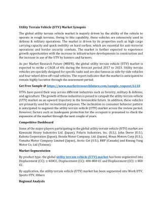
This report presents the Rocker Bogie mechanism that is being currently used for mars exploration rovers. This includes the comparison between the six wheel six motor rocker bogie and eight wheel eight motor rocker bogie. The data are collected for various surface conditions so that the rover can be used as an emergency supply vehicle in case of road blocks during landslides or can also be used to determine the safest route to cross the blockade. The main objective of the modified rover is to climb an obstacle of more than twice the wheel diameter and test it under the similar environment conditions as that of Mars in order to check the feasibility. Aayush Poudel | Yashaswi Khandelwal | Sayantan Das | K Venkadeshwaran | Karthik N "Design and Development of Multi-Terrain Vehicle" Published in International Journal of Trend in Scientific Research and Development (ijtsrd), ISSN: 2456-6470, Volume-2 | Issue-4 , June 2018, URL: https://www.ijtsrd.com/papers/ijtsrd14495.pdf Paper URL: http://www.ijtsrd.com/engineering/mechanical-engineering/14495/design-and-development-of-multi-terrain-vehicle/aayush-poudel<br>

E N D
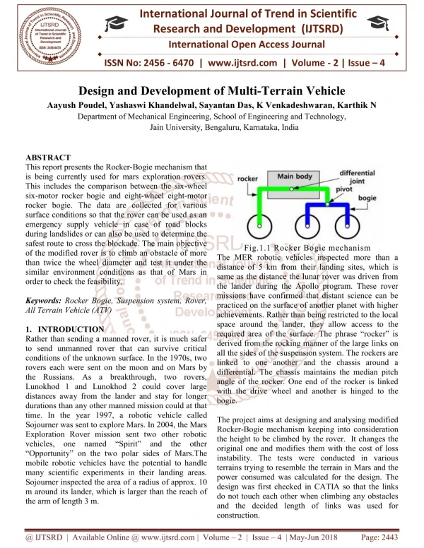
International Research Research and Development (IJTSRD) International Open Access Journal International Open Access Journal International Journal of Trend in Scientific Scientific (IJTSRD) ISSN No: 2456 ISSN No: 2456 - 6470 | www.ijtsrd.com | Volume Design and Development of Multi-Terrain Vehicle sh Poudel, Yashaswi Khandelwal, Sayantan Das, K Venkadeshwaran, Karthik N Department of Mechanical Engineering, School of Engineering and Technology, 6470 | www.ijtsrd.com | Volume - 2 | Issue – 4 Design and Development o Aayush Poudel, Yashaswi Khandelwal Department of Mechanical Engineering, School of Engineering Jain University Jain University, Bengaluru, Karnataka, India Terrain Vehicle , K Venkadeshwaran, Karthik N and Technology, ABSTRACT This report presents the Rocker-Bogie mechanism that is being currently used for mars exploration rovers. This includes the comparison between the six six-motor rocker bogie and eight-wheel eight rocker bogie. The data are collected for various surface conditions so that the rover can be used as an emergency supply vehicle in case of road blocks during landslides or can also be used to determine the safest route to cross the blockade. The main objective of the modified rover is to climb an obstacle of more than twice the wheel diameter and test it under the similar environment conditions as that of Mars in order to check the feasibility. Keywords: Rocker Bogie, Suspension system, Rover, All Terrain Vehicle (ATV) 1.INTRODUCTION Rather than sending a manned rover, it is much safer to send unmanned rover that can survive critical conditions of the unknown surface. In the 1970s, two rovers each were sent on the moon and on Mars by the Russians. As a breakthrough, two rovers, Lunokhod 1 and Lunokhod 2 could cover large distances away from the lander and stay for longer durations than any other manned mission could at that time. In the year 1997, a robotic vehicle calle Sojourner was sent to explore Mars. In 2004, the Mars Exploration Rover mission sent two other robotic vehicles, one named “Spirit” and the other “Opportunity” on the two polar sides of Mars. mobile robotic vehicles have the potential to handle many scientific experiments in their landing areas. Sojourner inspected the area of a radius of approx. 10 m around its lander, which is larger than the reach of the arm of length 3 m. Bogie mechanism that is being currently used for mars exploration rovers. This includes the comparison between the six-wheel wheel eight-motor rocker bogie. The data are collected for various surface conditions so that the rover can be used as an emergency supply vehicle in case of road blocks during landslides or can also be used to determine the to cross the blockade. The main objective of the modified rover is to climb an obstacle of more than twice the wheel diameter and test it under the similar environment conditions as that of Mars in Fig.1.1 Rocker Bogie The MER robotic vehicles inspected more than a distance of 5 km from their landing sites, which is same as the distance the lunar rover was driven from the lander during the Apollo program. These rover missions have confirmed that distant science can be practiced on the surface of another planet with higher achievements. Rather than being restricted to the local space around the lander, they allow access to the required area of the surface. The phrase “rocker” is derived from the rocking manner of the large all the sides of the suspension system. The rockers are linked to one another and the chassis around a differential. The chassis maintains the median pitch angle of the rocker. One end of the rocker is linked with the drive wheel and another is hi bogie. The project aims at designing and Rocker-Bogie mechanism keeping the height to be climbed by the rover. It changes the original one and modifies them with the cost of loss instability. The tests were terrains trying to resemble the terrain power consumed was calculated design was first checked in CATIA so that the links do not touch each other when climbing and the decided length of links construction. Bogie mechanism The MER robotic vehicles inspected more than a distance of 5 km from their landing sites, which is same as the distance the lunar rover was driven from the lander during the Apollo program. These rover missions have confirmed that distant science can be acticed on the surface of another planet with higher achievements. Rather than being restricted to the local space around the lander, they allow access to the required area of the surface. The phrase “rocker” is derived from the rocking manner of the large links on all the sides of the suspension system. The rockers are another and the chassis around a differential. The chassis maintains the median pitch angle of the rocker. One end of the rocker is linked with the drive wheel and another is hinged to the Suspension system, Rover, Rather than sending a manned rover, it is much safer to send unmanned rover that can survive critical conditions of the unknown surface. In the 1970s, two and on Mars by the Russians. As a breakthrough, two rovers, Lunokhod 1 and Lunokhod 2 could cover large distances away from the lander and stay for longer durations than any other manned mission could at that time. In the year 1997, a robotic vehicle called Sojourner was sent to explore Mars. In 2004, the Mars Exploration Rover mission sent two other robotic vehicles, one named “Spirit” and the other “Opportunity” on the two polar sides of Mars.The mobile robotic vehicles have the potential to handle cientific experiments in their landing areas. Sojourner inspected the area of a radius of approx. 10 m around its lander, which is larger than the reach of The project aims at designing and analysing modified keeping into consideration the rover. It changes the them with the cost of loss instability. The tests were conducted in various the terrain in Mars and the was calculated for the design. The first checked in CATIA so that the links not touch each other when climbing any obstacles and the decided length of links was used for @ IJTSRD | Available Online @ www.ijtsrd.com @ IJTSRD | Available Online @ www.ijtsrd.com | Volume – 2 | Issue – 4 | May-Jun 2018 Jun 2018 Page: 2443
International Journal of Trend in Scientific Research and Development (IJTSRD) ISSN: 2456-6470 motor in ANSYS. All the results in the analysis were analysed for static analysis. 3.PROBLEM STATEMENT The major limitation of current rocker-bogie is its inability to climb steps more than twice the wheel diameter. Having only one movable joint with two tyres, the height climbed is limited. The uneven terrain keeps on displacing the cg of vehicle. Hence the design should be so made that the cg, even when displaced, remains under the critical value maintaining the stability. When the front tyres face an obstacle the second tyre pushes it forward but the third tyre pulls it back down unless the link of the front tyre makes angle of more than 90 degrees with the vertical. For rocker-bogie there is a limitation in angle after which the vehicle is overturned. Generally the angle for efficient traversing is 45 degrees but with some design modifications, the rocker can go uphill of more than 50 degrees. 4.OBJECTIVES To construct and analyse the six-wheel six-motor Rocker-Bogie rover. To construct and analyze the modified eight-wheel eight-motor rover. To compare the power consumption and time for both the rovers. To observe if the new model can climb more than twice the dia of wheel. 5.METHODOLOGY 2.LITERATURE SURVEY 1.P. Panigrahi, A. Barik, Rajneesh R. & R. K. Sahu, “Introduction of Mechanical Gear Type Steering Mechanism to Rocker Bogie” This paper explains about a physical model of the rocker- bogie vehicle called Lightweight Survivable Rover (LSR). A proficient way of determining the kinematics and force analysis is used to solve problems like actuator saturation and tire-slip considerations. 2.A. Bhole, S., S. H. Turlapati, Raja shekhar V. S, J. Dixit, S. V. Shah, Madhava Krishna K, “Design of a Robust Stair Climbing Compliant Modular Robot to Tackle Overhang on Stairs” This paper focuses on the challenge that will permit the mobility of MER to stow within limited space available and deploy into a safe configuration. After extensive testing with different joint and latch designs, they were able to successfully meet the requirements placed on it by the flight system. 3.M. D. Manik, A. S. Chauhan, S. Chakraborty, V. R. Tiwari, “Experimental Analysis of climbing stairs with the rocker-bogie mechanism” The eastern coast of Malaysia encountered a immense flood from bulky downpour, resulting in vast damage and caused irreplaceable losses. The flood fetches the garbage, soil and fallen trees along the way, destroying the road and building structures. This situation provides problems to the rescue force carrying aids and food during the post disaster management. The research paper suggested an effective inclined motion control of an amphibious vehicle when travelling on rough terrains. 4.Hayati, S., “The Rocky 7 Rover: A Mars Science craft Prototype” This paper deals with the slope analysis of the Rocker-Bogie mechanism to determine the maximum height and angle at which it can climb. It was found that the designed and manufactured model could the angle up to 45 degrees and during stair climbing test for length less than 375mm, system could not climb the stair. 5.Schenker, P., “Lightweight Rovers for Mars Science Exploration and Sample Return” In this work the proposed steering mechanism was designed and the modelling was done in CATIA (V-5) and the same was analysed for static analysis for the proposed torque condition of the Fig.5.1 Methodology @ IJTSRD | Available Online @ www.ijtsrd.com | Volume – 2 | Issue – 4 | May-Jun 2018 Page: 2444
International Journal of Trend in Scientific Research and Development (IJTSRD) ISSN: 2456 International Journal of Trend in Scientific Research and Development (IJTSRD) ISSN: 2456 International Journal of Trend in Scientific Research and Development (IJTSRD) ISSN: 2456-6470 5.1 Design Consideration 6 Wheel ATV Fig.5.2 Design for 6 wheel all-terrain vehicle terrain vehicle (c) Stage-III with second tyre onobstacle III with second tyre onobstacle Distance b/w tyres = 210 mm From Pythagoras Theorem, (Hypotenuse)2= (perpendicular)2 + (base) 1202 = x2 + x2 x = 148.9mm ~ 150 mm Motor Clearance = 14 mm Connector Clearance = 13 mm Pipe length (front tyres) =150-14-13 Pipe length (back tyres) = 180 mm Carrier length = 120 mm 8 Wheel ATV Fig.5.4 CATIA model design, the linklengths were(a) first joint linkages 12.9 cm,(b) second joint linkages 29.9 cm and (c) forlast tyre link 38.8 cm. Motor Speed Total Weight of Vehicle = 25 kg Number of motors = 6 Work load per motor = 25/6 = 4.17 ~ 5 kg Coefficient of friction = 0.3 Frictional force = 5*0.3*9.81 = 14.7 N Power required = F*v/efficiency = 14.7*.25/0.8 = 4.6 W Motor rpm = 60 P/ (2πFr) = 60*4.6/(2*3.14*14.7*.05) = 59.76 i.e. 60 rpm 5.2Materials Used a.PVC pipe (22.2 mm and 25.4 mm diameter) b.Connectors (L-type and V- c.plastic tyres (4 inch diameter) d.Hose clamp e.Connecting wires f.Lead Acid Battery (12 V, 1.3 Ah) g.Wooden blocks h.Screws i.Pipes adhesive Drilling Machine 5.3 Experiment Method 6 Wheel and 8 Wheel ATV Tests Steps obstacle for Rocker- Rectangular concrete blocks of different heights were used to make the steps of approx. 1 m as shown in the figure. This terrain was made to check the ability of vehicle to climb vertical obstacles. Sand hill obstacle for Rocker A terrain of inclination angle of about 40 degrees was made with sand as shown in the figure. The length of the terrain was approximately 1 m. Gravel obstacle for Rocker Gravel obstacle for Rocker-Bogie Fig.5.4 CATIA model design, the linklengths were(a) first joint linkages 12.9 cm,(b) second joint linkages 29.9 cm and (c) forlast tyre link 38.8 cm. (base)2 Total Weight of Vehicle = 25 kg = 4.17 ~ 5 kg = 123 mm Power required = F*v/efficiency = 14.7*.25/0.8 = 60*4.6/(2*3.14*14.7*.05) = 59.76 i.e. 60 rpm PVC pipe (22.2 mm and 25.4 mm diameter) -type) Fig.5.3 Design for 8 Wheel ATV Fig.5.3 Design for 8 Wheel ATV plastic tyres (4 inch diameter) Lead Acid Battery (12 V, 1.3 Ah) j. (a) Stage-I with first tyre on obstacle I with first tyre on obstacle 6 Wheel and 8 Wheel ATV Tests -Bogie Rectangular concrete blocks of different heights were used to make the steps of approx. 1 m as shown in the figure. This terrain was made to check the ability of vehicle to climb vertical obstacles. Sand hill obstacle for Rocker-Bogie n of inclination angle of about 40 degrees was made with sand as shown in the figure. The length of the terrain was approximately 1 m. (b) Stage-II with second tyre onobstacle II with second tyre onobstacle @ IJTSRD | Available Online @ www.ijtsrd.com @ IJTSRD | Available Online @ www.ijtsrd.com | Volume – 2 | Issue – 4 | May-Jun 2018 Jun 2018 Page: 2445
International Journal of Trend in Scientific Research and Development (IJTSRD) ISSN: 2456-6470 A terrain of inclination of about 35-40 degrees was constructed as shown in the figure, the length being the same of about 1 m Pit obstacle for Rocker-Bogie A terrain of inclination angle of about 40 degrees was made with sand as shown in the figure. The length of the terrain was approximately 1 m 5.4 Calculations 6 Wheel ATV Steps obstacle Voltage before running (V1) = 11.38 V Voltage after running (V2) = 11.07 V Current (I) = 1.3 A Voltage consumed (V) = V1 - V2 = 11.38 – 11.07= 0.31 V Power consumed (P) = I * V = 1.3 * 0.31= 0.403 W Sand hill obstacle Voltage before running (V1) = 11.07 V Voltage after running (V2) = 10.52 V Current (I) = 1.3 A Voltage consumed (V) = V1 - V2 = 11.07 – 10.52 = 0.55 V Power consumed (P) = I * V = 1.3 * 0.55= 0.715 W Gravel obstacle Voltage before running (V1) = 10.52 V Voltage after running (V2) = 10.09 V Current (I) = 1.3 A Voltage consumed (V) = V1 - V2 = 10.52-10.09= 0.43 V Power consumed (P) = I * V = 1.3 * 0.43= 0.559 W Height climbed = 10cm 8 Wheel ATV Steps obstacle Voltage before running (V1) = (11.45+11.45) V = 22.90 V Voltage after running (V2) = (11.41+11.41) V = 22.82 V Current (I) = 1.3 A Voltage consumed (V) = V1 - V2 = 22.90 -22.82 = 0.08 V Power consumed (P) = I * V = 1.3 * 0.08 = 0.104 W Sand hill obstacle Voltage before running (V1) = (11.41+11.41) V = 22.82 V Voltage after running (V2) = (11.39+11.39) V = 22.78 V Current (I) = 1.3 A Voltage consumed (V) = V1 - V2 = 22.82 – 22.78 = 0.04 V Power consumed (P) = I * V = 1.3 * 0.04 = 0.052 W Gravel obstacle Voltage before running (V1) = (11.39+11.39) V= 22.78 V Voltage after running (V2) = (11.36+11.37) V = 22.73 V Current (I) = 1.3 A Voltage consumed (V) = V1 - V2 = 22.78 - 22.73= 0.05 V Power consumed (P) = I * V = 1.3 * 0.05 = 0.065 W Pit obstacle Voltage before running (V1) = (11.36+11.37) V = 22.73 V Voltage after running (V2) = (11.34+11.35) V = 22.69 V Current (I) = 1.3 A Voltage consumed (V) = V1 - V2 = 22.73 – 22.69 = 0.04 V Power consumed (P) = I * V = 1.3 * 0.04 = 0.052 W Height climbed = 25 cm 6.RESULTS AND DISCUSSIONS @ IJTSRD | Available Online @ www.ijtsrd.com | Volume – 2 | Issue – 4 | May-Jun 2018 Page: 2446
International Journal of Trend in Scientific Research and Development (IJTSRD) ISSN: 2456-6470 Fig.6.1 Final Prototype(6-wheel ATV) stability because of more height of vehicle from ground level that increases the distance of cg. The power consumption is found to be lowest on sand hill and max when climbing the steps for both the designs but since the modified rover uses more number of wheels and motor the power consumption is high. Environment selected for tests were taken that resembles the condition on mars to see the rover’s feasibility. Pit test and sand hill test shows that the vehicle can climb a maximum elevation of about 50 degrees. REFERENCES 1.P. Panigrahi, A. Barik, Rajneesh R. & R. K. Sahu, “Introduction of Mechanical Gear Type Steering Mechanism to Rocker Bogie”, Imperial Journal of Interdisciplinary Research (IJIR) Vol-2, Issue-5, ISSN: 2454-1362, 2016. Fig.6.2 Final Prototype (8 wheel ATV) TABLE 1 POWER CONSUMPTION Terrain Time taken (s) Power consumed (Watts) 0.403 0.725 0.559 2.A. Bhole, S. H. Turlapati, Raja shekhar V. S, J. Dixit, S. V. Shah, Madhava Krishna K, “Design of a Robust Stair Climbing Compliant Modular Robot to Tackle Overhang on Stairs” arXiv:1607.03077v1 [cs.RO], 11 Jul 2016. Steps Sand hill Gravel Table 6.1 Power consumption 6 wheel ATV TABLE 2 Power Consumption Terrain Time taken (s) 8 20 15 3.M. D. Manik, A. S. Chauhan, S. Chakraborty, V. R. Tiwari, “Experimental Analysis of climbing stairs with the rocker-bogie mechanism”, Vol-2 Issue-2 P.No. 957-960IJARIIE-ISSN(O)- 2395-4396, 2016. Power consumed (Watts) 0.08 0.052 0.065 0.054 Steps Sand hill Gravel Pit 6 4 4 4 4.Hayati, S., et. al., “The Rocky 7 Rover: A Mars Sciencecraft Prototype”, Proceedings of the1997 IEEE International Conference on Robotics and Automation, pp. 2458-64, 1997. Table 6.2Power consumption 8 wheel ATV The height climbed by modified design was more than two times the diameter thus having an advantage over single rocker but its stability is a major issue. The inefficiency of the model was due to several factors like loose connections, tyre grip, insufficient torque, lack of direction control, and the mechanism where 3rd and 4th tyres pull the front tyres back when on obstacle. 7. CONCLUSION The design under consideration shows it was practically able to climb twice the wheel diameter because of the limitations explained above. On the other hand the single existing rocker bogie rover has its limitation to climb a maximum of twice the diameter of wheel. Changing the design has resulted in increase of height climbed but has reduced its 5.Schenker, P., et. al., “Lightweight Rovers for Mars Science Exploration and Sample Return, “Intelligent Robots and Computer Vision XVI, SPIE Proc. 3208, Pittsburg, PA, October, 1997. 6.Hacot, H., The Kinematic Analysis and Motion Control of a Planetary Rover, Master’sThesis, Department of Mechanical Massachusetts Institute Cambridge, MA,May, 1998. Engineering, Technology, of 7.Farritor S., Hacot H., Dubowsky S., “Physics Based Planning for Planetary Exploration”, Proceedings of the 1998 IEEE International Conference on Robotics and Automation @ IJTSRD | Available Online @ www.ijtsrd.com | Volume – 2 | Issue – 4 | May-Jun 2018 Page: 2447