Download
1 / 4
40 likes | 110 Views
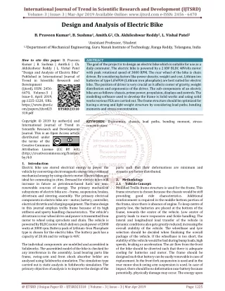
The goal of the project is to design an electric bike which is suitable for use as a daily commuter. The electric bike is powered by a 2 KW BLDC 48Volts motor with peak rotational speed of 3000 RPM. The rear wheel of the bike is chain driven. By considering factors like power density, weight and cost, Lithium ion batteries of type LiFePO4 Lithium iron phosphate are best suited for electric bike. The position of driver is very crucial as it affects center of gravity, weight distribution and ergonomics of the driver. The sub components of an electric bike are as follows chassis, prime power, propulsion, displays and controls. The modelling software used to develop the frame is Solid works and using solid works various FEA are carried out. The frame structure should be optimized for having a strong and light weight structure by considering load paths, bending moments and stress concentration. B. Praveen Kumar | B. Sushma | Amith.G | Ch. Akhileshwar Reddy | L. Vishal Patel "Design and Analysis of Electric Bike" Published in International Journal of Trend in Scientific Research and Development (ijtsrd), ISSN: 2456-6470, Volume-3 | Issue-3 , April 2019, URL: https://www.ijtsrd.com/papers/ijtsrd23310.pdf Paper URL: https://www.ijtsrd.com/engineering/mechanical-engineering/23310/design-and-analysis-of-electric-bike/b-praveen-kumar<br>

E N D
International Journal of Trend in Scientific Research and Development (IJTSRD) Volume: 3 | Issue: 3 | Mar-Apr 2019 Available Online: www.ijtsrd.com e-ISSN: 2456 - 6470 Design and Analysis of Electric Bike B. Praveen Kumar1, B. Sushma1, Amith.G2, Ch. Akhileshwar Reddy2, L. Vishal Patel2 1Assistant Professor, 2Student 1,2Department of Mechanical Engineering, Guru Nanak Institute of Technology, Ranga Reddy, Telangana, India How to cite this paper: B. Praveen Kumar | B. Sushma | Amith.G | Ch. Akhileshwar Reddy | L. Vishal Patel "Design and Analysis of Electric Bike" Published in International Journal of Trend in Scientific Research and Development (ijtsrd), ISSN: 2456- 6470, Volume-3 | Issue-3, April 2019, pp.1225-1228, URL: https://www.ijtsrd.c om/papers/ijtsrd23 310.pdf Copyright © 2019 by author(s) and International Journal of Trend in Scientific Research and Development Journal. This is an Open Access article distributed under the terms of the Creative Commons Attribution License (CC BY 4.0) (http://creativecommons.org/licenses/ by/4.0 1.Introduction Electric bike use stored electrical energy to power the vehicle by converting electromagnetic energy into rotational mechanical energy by using electric motor. Electric bikes are ideal for commuting in cities. Demand for electric bikes will increase in future as petroleum-based fuels are non- renewable sources of energy. The primary mechanical subsystems of electric bike are – frame, suspension, brakes, drivetrain and steering assembly. The primary electrical components in electric bike are – motor, battery, controller, electrical throttle and charging equipment. The frame design in this journal employs trellis frame because of its high stiffness and sporty handling characteristics. The vehicle’s drivetrain is rear wheel drive and power is transmitted from motor to wheel using sprockets and chain. The vehicle is powered by BLDC motor which delivers peak power of 2000 watts at 3000 rpm. Battery pack of Lithium–Iron Phosphate type is chosen for the electric bike. The battery pack has a capacity of 28 Ah and its voltage is 48V. The individual components are modelled and assembled in Solidworks. The assembled model of the bike is checked for any interference in the assembly. Load bearing parts like frame, swing-arm and front shock absorber holder are analysed using Solidworks simulation. The simulation type carried out is static analysis in Solidworks simulation. The primary objective of analysis is to improve the design of the ABSTRACT The goal of the project is to design an electric bike which is suitable for use as a daily commuter. The electric bike is powered by a 2 KW BLDC 48Volts motor with peak rotational speed of 3000 RPM. The rear wheel of the bike is chain driven. By considering factors like power density, weight and cost, Lithium ion batteries of type LiFePO4 (Lithium iron phosphate) are best suited for electric bike. The position of driver is very crucial as it affects center of gravity, weight distribution and ergonomics of the driver. The sub-components of an electric bike are as follows: chassis, prime power, propulsion, displays and controls. The modelling software used to develop the frame is Solid works and using solid works various FEA are carried out. The frame structure should be optimized for having a strong and light weight structure by considering load paths, bending moments and stress concentration. KEYWORDS: Ergonomics, chassis, load paths, bending moment, stress- concentration. IJTSRD23310 parts such that their deformations are minimum and stresses are better distributed. 2.Methodology 2.1 Vehicle Concept: Modified Trellis frame structure is used for the frame. This frame structure is chosen because the chassis would be stiff providing good ride characteristics. reinforcement is required in the middle-bottom portion of the frame, since there is absence of engine. To keep centre of gravity low, the batteries are placed at the bottom of the frame, towards the centre of the vehicle. Low centre of gravity leads to more responsive and fickle handling. The lateral and longitudinal load transfer of the vehicle in dynamic conditions also gets greatly reduced, increasing the overall stability of the vehicle. The wheelbase and tyre selection should be decided when finalizing the overall package of the vehicle. If the wheelbase is too short, the stability of the vehicle would be bad during bump loads, high speeds, braking or acceleration. The air flow from the front of the bike should be diverted such that there is adequate cooling for batteries and motor. The frame should be designed such that battery can be easily removable in case of replacement. In the front fork suspension is used and in the rear mono-shock swing arm suspension is used. In case of impact, there should be no deformation near battery because potentially, physically damage may occur. The energy upon Additional @ IJTSRD | Unique Paper ID – IJTSRD23310 | Volume – 3 | Issue – 3 | Mar-Apr 2019 Page: 1225
International Journal of Trend in Scientific Research and Development (IJTSRD) @ www.ijtsrd.com eISSN: 2456-6470 impact should be dissipated elsewhere in the frame to prevent damage to battery pack. 2.2 Electric bike frame: The motor is held by the frame which kind of encircles the motor while connecting the steering head to the swing arm in the shortest way. The frames are light in weight and handling is much sportier on this type of frame. Slight reinforcement is required to give additional strength as electric bike has no engine. The Trellis frame is similar in its basic concept to the perimeter frame. This frame’s primary objective, too, is to connect the steering head with the swing- arm as directly as possible. 2.3 Battery: Lithium–Iron Phosphate type battery is chosen for the electric bike. This type of battery has high energy density of 100 Wh/kg. They have a high discharge rate of 30C. These batteries do not explode if they are abused. This is a better alternative for Lithium polymer batteries as they have risk of exploding [5]. 2.4 Materials: The material chosen for bike frame and swing arm is AISI Chromoly 4130 and AISI Aluminium 6061-T6 for the front shock absorber holder . 3.Modelling of Frame and Other Components Using weldments module in Solid works, tubular structures are made along the wireframe. Three different tubular cross- sections were used for the frame. 1-inch diameter tube of 1.6mm thickness, 24.5mm diameter tube of 1mm thickness and 2-inch diameter tube of 2mm thickness are used in the frame model. The mounts for swing arm are behind the motor. Swing arm mounts and motor positioning needs to be carefully done because the effective chain length will vary as the swing arm moves due to suspension travel. They are placed close to each other and towards the line connecting motor centre to the rear wheel. The swing arm positioning and its mounts does not cause any interference with the chain under dynamic conditions. Tubular extensions from the frame along with metal plates are used to mount the motor onto the frame. Multiple tubes are connected at the node where rear shock absorber is mounted. This is to transmit forces effectively and increase overall chassis stiffness. A tube is attached to the node which is along the direction of force from the suspension to make load distribution more linear and effective. 3.1 Other components like motor, battery, swing-arm, handle, shockabsorber (rear amd front), front shock absorber holder and wheel assembly are modelled in Solidworks. 4.Analysis of Frame and Other Components Analysis of frame is done in Solid works Simulation. Blended curvature-based mesh is used for meshing of frame. The total number of nodes are 112839 and the total number of elements are 62652. Suspension loads and the loads due to driver and pillion rider are tested. The primary objective of frame is to have good stiffness. 4.1 Static analysis of frame with rear suspension loads Force of 3500N is acted in the rear suspension mount. This is much above practical scenario and it is meant to demonstrate worst case scenario of peak forces. Rear suspension loads increase with added weight of pillion rider and driver. Hitting a pot hole at high speed with a heavy pillion passenger would result in high loads. Modelling of other components Fig.: Stress Concentration in the Front Section of Frame Due to Rear Suspension Load Fig.: Stress Concentration at Rear Portion of The Frame Due to Rear Suspension Load S. No. Property 1 Yield strength 2 Maximum stress 3 Maximum displacement 4 Maximum strain Table 4: Results of Static analysis of frame with rear suspension loads Value 4.6e+08 2.624e+08 N/m2 7.948e-01 9.119e-04 Units N/m2 mm N/A 4.2 Static analysis of frame with front suspension load Front suspension load of 3500N is acting on the frame. Such high forces may act when hitting a bump or pothole at a high speed. Usually, front suspension gets affected as it absorbs most of the initial energy when having an impact with bump Fig.: Isometric View of The Frame @ IJTSRD | Unique Paper ID – IJTSRD23310 | Volume – 3 | Issue – 3 | Mar-Apr 2019 Page: 1226
International Journal of Trend in Scientific Research and Development (IJTSRD) @ www.ijtsrd.com eISSN: 2456-6470 or pothole. If under braking a bump or pothole is hit, it further increases suspension loads highly as longitudinal weight transfer towards front takes place under braking. Fig.: Stress Concentration of Frame at Rear Suspension Mount Due to Driver and Pillion Rider Loads S. No. 1 Yield strength 2 Maximum stress Maximum displacement 4` Maximum strain Table: Results of Static analysis of frame with driver and pillion rider loads 4.4 Static analysis of Front shock-absorber holder The loads from the front suspension travels through the front shock-absorber holder. It clamps the front fork and the clamping force acts on it. The total clamping force is assumed to be 400N. Suspension load of 2000N acts on this part. Standard mesh type is used. The total number of nodes are 88980 and the total number of elements are 56770. Fig.: Von-Mises Stress Distribution Acting on Rear Section of The Frame Due to Front Suspension Load Property Value Units 4.6e+08 4.333e+07 N/m2 N/m2 3 1.463e-01 mm 1.213e-04 N/A Fig.: Displacement of The Frame in mm Due to Front Suspension Load S. No. Property 1 Yield strength 2 Maximum stress 3 Maximum displacement 4 Maximum strain Table: Results of Static analysis of frame with front suspension load 4.3 Static analysis of frame with driver and pillion rider loads The weight of driver and pillion rider are 100kg each and it acts along the upper portion of the frame where they are seated. Total of 2000N of force is acting on frame vertically downwards. Value 4.6e+08 2.624e+08 N/m2 7.948e-01 9.119e-04 Units N/m2 mm N/A Fig.: Von Mises Stress Distribution of Front Shock- Absorber Holder (Isometric View) Fig.: Displacement in mm of Front Shock-Absorber Holder (Rear Isometric View) Fig.: Displacement in mm of the Frame Due to Driver and Pillion Rider Loads @ IJTSRD | Unique Paper ID – IJTSRD23310 | Volume – 3 | Issue – 3 | Mar-Apr 2019 Page: 1227
International Journal of Trend in Scientific Research and Development (IJTSRD) @ www.ijtsrd.com eISSN: 2456-6470 Table: Results of Static analysis of Front shock-absorber holder S. No. 1 Yield strength 2 Maximum stress 3 Maximum displacement 4 Maximum strain 5.Result The individual parts of electric bike are modelled. Crucial load bearing components like frame, front shock-absorber holder and swing-arm are analysed by applying static load. The load applied on analysed components are higher than normal, and it represents worst case scenario loading conditions. The assembled sub-components in the vehicle are moved to check if there are any constraints and the assembly is functioning as intended. The frame is very stiff and deformations due to external loads are minimal. The centre of gravity along its lateral axis is in the central plane of the bike, which helps in predictable handling and good balance. The driver is positioned such that the weight distribution of the vehicle along longitudinal axis is close to 45:55. Overall packaging of vehicle is done compactly without causing any interferences. The packaging and assembly of individual components is done using Solid works assembly. All the components were able to mate appropriately without causing any interferences or problems while mating. The load paths in the frame are optimized using trusses and bending moments are minimal in the frame. The overall centre of gravity of the frame is low due to positioning of motor and battery. 6.Conclusion The overall design of electric bike is effective for initial iteration of design. A design requires numerous iterations, testing and prototyping to make a good design. Few parameters are very well optimized in the project like, frame stiffness, load paths and overall weight of the frame. The performance standards of the frame are good enough for a sports bike The factor of safety is much higher than 1. The overall bike structure is strong enough to withstand loads even in the worst-case scenario where excessive loads are developed. The stress concentration near the holes at suspension mounts and front shock-absorber holder is high. This can be reduced by simply using washers to better distribute the stress across the surface area. 7.References [1]Ranjan Kumar1, Munna Kumar2, Pradyumn Sah3, Mustaim Alam4, “Design and Fabrication of Electric Bicycle”, 2018. Property Value Units 2.75e+08 N/m2 1.433e+08 N/m2 1.757e+00 mm 4.603e-04 N/m2 N/m2 mm N/A 4.5 The suspension loads from the rear tyre travels from the wheel to swing-arm and then it gets transmitted into frame and shock-absorber. This part is heavily stressed due to development of high bending moments. Force of 2000N is applied on the swing-arm in static analysis. Standard mesh is applied. The total number of nodes are 58651 and the total number of elements are 29263. Static analysis of Swing-arm Fig.: Von Mises Stress Distribution in Swing-Arm Fig.: Displacement of Swing-Arm in mm S. No. 1 2 3 4 Property Value Units Yield strength Maximum stress Maximum displacement Maximum strain Table: Results of Static analysis of swing-arm 2.75e+08 N/m2 1.433e+08 N/m2 1.757e+00 mm 4.603e-04 N/m2 N/m2 mm N/A [2]Mitesh M. Trivedi1, Manish K. Budhvani2, Kuldeep M. Sapovadiya3, Darshan H. Pansuriya4, Chirag D. Ajudiya5, “Design & Development of E-Bike - A Review” Volume 1 Issue 5, NOV 2017. 4.6 Various components are assembled together in Solid works assembly. Chain is excluded from assembly as the number of links in the chain is to be determined by adjusting tension appropriately. Assembly of E-Bike [3]Deep R Prajapati, Kunjan Shinde, Abhishek Mhaske, Aniket Prabhu, “DESIGN AND FABRICATION OF ELECTRIC BIKE”, Volume 8, Issue 3, March 2017. [4]Vivek V Kumar1, Karthik A2, Ajmal Roshan3, Akhil J Kumar4, “Design and Implementation of Electric Assisted Bicycle with Self Recharging Mechanism”, Volume 3, Special Issue 5, July 2014. [5]William C. Morchin and Henry Oman, 2006, "Electric Bicycles: A Guide to Design and Use”, John Wiley & Sons, Inc., Hoboken, New Jersey. Fig.: Assembly of Electric Bike (Isometric View) @ IJTSRD | Unique Paper ID – IJTSRD23310 | Volume – 3 | Issue – 3 | Mar-Apr 2019 Page: 1228