Download
1 / 3
30 likes | 56 Views
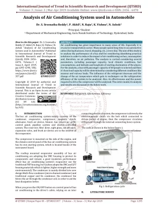
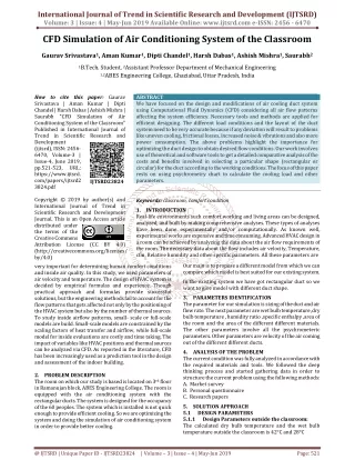
We have focused on the design and modifications of air cooling duct system using Computational Fluid Dynamics CFD considering all air flow patterns affecting the system efficiency. Necessary tools and methods are applied for efficient designing. The different load conditions and the layout of the duct system need to be very accurate because if any deviation will result to problems like uneven cooling, frictional losses, increased noise and vibrations and also more power consumption. The above problems highlight the importance for optimizing the duct design to obtain desired flow conditions. Our work involves use of theoretical and software tools to get a detailed comparative analysis of the costs and benefits involved in selecting a particular shape rectangular or circular for the duct according to the working conditions. The focus of this paper rests on using psychrometry chart to calculate the cooling load and other parameters. Gaurav Srivastava | Aman Kumar | Dipti Chandel | Harsh Dabas | Ashish Mishra | Saurabh "CFD Simulation of Air Conditioning System of the Classroom" Published in International Journal of Trend in Scientific Research and Development (ijtsrd), ISSN: 2456-6470, Volume-3 | Issue-4 , June 2019, URL: https://www.ijtsrd.com/papers/ijtsrd23824.pdf Paper URL: https://www.ijtsrd.com/engineering/mechanical-engineering/23824/cfd-simulation-of-air-conditioning-system-of-the-classroom/gaurav-srivastava<br>

E N D
International Journal of Trend in Scientific Research and Development (IJTSRD) Volume: 3 | Issue: 4 | May-Jun 2019 Available Online: www.ijtsrd.com e-ISSN: 2456 - 6470 CFD Simulation of Air Conditioning System of the Classroom Gaurav Srivastava1, Aman Kumar1, Dipti Chandel1, Harsh Dabas1, Ashish Mishra1, Saurabh2 1B.Tech. Student, 2Assistant ProfessorDepartment of Mechanical Engineering 1,2ABES Engineering College, Ghaziabad, Uttar Pradesh, India How to cite this paper: Gaurav Srivastava | Aman Kumar | Dipti Chandel | Harsh Dabas | Ashish Mishra | Saurabh "CFD Simulation of Air Conditioning System of the Classroom" Published in International Journal of Trend in Scientific Research and Development (ijtsrd), ISSN: 2456- 6470, Volume-3 | Issue-4, June 2019, pp.521-523, URL: https://www.ijtsrd. com/papers/ijtsrd2 3824.pdf Copyright © 2019 by author(s) and International Journal of Trend in Scientific Research and Development Journal. This is an Open Access article distributed under the terms of the Creative Commons Attribution License (CC BY 4.0) (http://creativecommons.org/licenses/ by/4.0) very important for determining human comfort conditions and inside air quality. In this study, we used parameters of air velocity and temperature. The design of HVAC system is decided by empirical formulas and experience. Though practical approach and formulas provide successful solutions, but the engineering methods fail to account for the flow patterns that gets affected not only by the positioning of the HVAC system but also by the number of thermal sources. To study inside airflow patterns, small- scale or full-scale models are build. Small-scale models are constrained by the scaling factors of heat transfer and airflow, while full-scale model for inside evaluations are costly and time taking. The impact of variables like HVAC positions and thermal sources can be analyzed via CFD. As reported in the literature, CFD has been increasingly used as a prediction tool in the design and assessment of the indoor building. 2.PROBLEM DESCRIPTION The room on which our study is based is located on 3rd floor in Ramanujan block, ABES Engineering College. The room is equipped with the air conditioning system with the rectangular ducts. The system is designed for the occupancy of the 60 peoples. The system which is installed is not quick enough to provide efficient cooling. So we are optimizing the system and doing the simulation of air conditioning system in order to provide better cooling. ABSTRACT We have focused on the design and modifications of air cooling duct system using Computational Fluid Dynamics (CFD) considering all air flow patterns affecting the system efficiency. Necessary tools and methods are applied for efficient designing. The different load conditions and the layout of the duct system need to be very accurate because if any deviation will result to problems like uneven cooling, frictional losses, increased noise & vibrations and also more power consumption. The above problems highlight the importance for optimizing the duct design to obtain desired flow conditions. Our work involves use of theoretical and software tools to get a detailed comparative analysis of the costs and benefits involved in selecting a particular shape (rectangular or circular) for the duct according to the working conditions. The focus of this paper rests on using psychrometry chart to calculate the cooling load and other parameters. Keywords: classroom, comfort condition 1.INTRODUCTION Real-life environments such comfortworking and living areas can be designed, analyzed, and built by making comprehensive analyses. These types of analyses have been done experimentally and/or computationally. As known well, experimental works are expensive and time consuming. Advanced HVAC design in a room can be achieved by analyzing the data about the air flow requirements of the room. The necessary data about the flow includes air velocity, Temperature, cfm, Relative humidity and other specific parameters. All these parameters are IJTSRD23824 Our main is to propose a different model from which we can compare which model is best suited for our existing system. In the existing system we have got rectangular duct so we want to give model with different duct shape. 3.PARAMETERS IDENTIFICATION The parameter for our simulation is sizing of the duct and air flow rate. The next parameter are wet bulb temperature ,dry bulb temperature , humidity ratio ,specific enthalpy ,area of the room and the area of the different different materials. The other parameters involve all the psychrometeric parameters. Other parameters are velocity of the air coming out of the different different ducts. 4.ANALYSIS OF THE PROBLEM The current condition was fully analyzed in accordance with the required materials and tools. We followed the deep thinking process and started gathering data in order to structure the current problem using the following methods: A. Market survey B. Personal questionnaire C. Research papers 5.SOLUTION APPROACH 5.1 DESIGN PARAMETERS 5.1.1 Design Parameters outside the classroom: The calculated dry bulb temperature and the wet bulb temperature outside the classroom is 42°C and 28°C @ IJTSRD | Unique Paper ID - IJTSRD23824 | Volume – 3 | Issue – 4 | May-Jun 2019 Page: 521
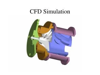
International Journal of Trend in Scientific Research and Development (IJTSRD) @ www.ijtsrd.com eISSN: 2456-6470 5.1.2 The desired dry bulb temperature inside the classroom is 24°C and desired relative humidity is 50%. There are four grill installed in the duct. The velocity of air from grill obtained is 4m/s. 5.2 CALCULATION Different types of heat load: Heat load from different walls ; 1. Exposed Wall, Q = U×A×ΔT = 3413.608 BTU/hr 2. North and South Wall, Q = 2×( U×A×ΔT) = 10976.229 BTU/hr 3. West Wall, Q = U×A×ΔT = 47430882 BTU/hr Heat load from the walls is 19133.7115 BTU/hr. Heat load from the roof, Q = U×A×ΔT = 20189.46 BTU/hr. Heat load from glass window, Q = U×A×ΔT = 1384.536 BTU/hr. Sensible heat load from people, Qs = 245×60 = 14700 BTU/hr Latent heat load from people, Ql = 155×60 = 9300 BTU/hr. Total heat load from people is 24000 BTU/hr. Total lighting load, Q = Watt/ft2 × Area of ft2 × 3.4 = 3935.56 BTU/hr. 5.3 SIMULATION 5.3.1 Establishment of Model: The dimensions of room are 31x26x7 (all dimensions are in feet). The dimensions of installed duct are 77x44x17 (all dimensions are in cm). The duct which is rectangular in shape is at the back of the classroom. There are four grills in the rectangular duct. The first grill is located at the 40cm from the right side, second grill is located at 75cm from the first grill, third grill is located at 1m from the second grill and last grill is located at the 110cm from the left 5.3.2 Boundary Conditions: The cubic feet per minute (CFM) at the inlet of the duct is 1.1m/s. The velocity of the air at the first grill is 3.9m/s, velocity of the air at the second grill is 3.6m/s, velocity of the air at the third grill is 4.2m/s and velocity at the last grill is 4m/s. Outside design conditions include outside dry bulb temperature at 42°C and wet bulb temperature at 28°C. The relative humidity of the room is 50%RH. 5.3.3 Model Meshing and Solver Parameter Setting: This study adopted the method for defining the meshing size function to guarantee the mesh quality of the model. Design Parameters inside the classroom: Meanwhile, mesh quantity was unlikely to be excessively large. First, the meshes of the significant surveyed surfaces (e.g., surfaces of the air inlets and exhaust outlets, as well as the heat flow surfaces with large heat flow) were divided into small sizes, thereby enabling the mesh densities on these surfaces to be relatively high. When the mesh function was defined, the meshes were divided from these critical surfaces toward the surrounding space at 1.1-fold growth rate. A total of 4,586,496 meshes and 846,589 nodes were generated after the calculation. Fig. 1 Mesh 5.3.4 Only the air-conditioning conditions in the summer were used due to the limited length of this study. The analog CFD calculation and analysis of the air-conditioning conditions were conducted at the representative 6:00, 8:00, and 13:00 time frames on the condition that the air supply temperature difference (9 °C) and air supply volume (111,630 m3/h) were guaranteed to be unchanged. The temperature field distributions of the classroom could be obtained based on the simulation results. Simulation Result Analysis Fig. 2 input of boundary conditions Fig. 3 Velocity contour @ IJTSRD | Unique Paper ID - IJTSRD23824 | Volume – 3 | Issue – 4 | May-Jun 2019 Page: 522
International Journal of Trend in Scientific Research and Development (IJTSRD) @ www.ijtsrd.com eISSN: 2456-6470 Fig. 7 duct with circular duct 7.RESULT DISCUSSION From this particular study we had found various results. This particular simulation helps us in determining various factors from which we can find efficient cooling. This simulation provide us that the use of air conditioning between 5-6 tonnes can provide better cooling at the peak conditions. 8.FUTURE ASPECTS Mathematical modelling of this work can be done with help of FEM. Various results can be obtained from that mathematical modelling. Various differential equations can provide the best results for the discussed work. 9.Conclusion: The CFD simulation is obtained for the air conditioning system. Various contours and plot has been obtained. The plot for the temperatures, velocity, and the streamline is obtained. These plots are used to obtain various conclusions. References: [1]Yin Hua, Guo Huafang, Lin Zhenrong, Zeng Bo CFD simulation of air conditioning system in of a metro station and research paper on energy saving operation scheme. Pages 1-6 Guangzhou, China 2017. Fig. 4 Velocity streamline Fig. 5 Pressure volume rendering 1 [2]Mahmoud Kassas Modelling and simulation of residential HVAC systems energy consumption. Page 1-10 Dhahran, Saudi Arabia 2015. [3]Chang Soon Kang, jong-II Park, Mignon Park, Jaeho Baek, Novel modelling and Control strategies for a HVAC system including carbon dioxide control, Suwon, Korea May 2014. [4]Raad Z. Homod HVAC system modelling types and the shortcomings of their applications. Page 1-11 Basrah, Iraq may 2013. Fig. 6 iteration chart [5]Jianmin Sun, Chundong Zahang< Zeyang Zhou Modelling and Simulation of chilled water system for central air conditioning , Beijing, China, october 2012. 6.Proposed model We had simulated the classroom with the rectangular duct. We had seen the results from above simulation. So we have proposed a new model with circular duct. And also if we consider the factor of infiltration then the duct with the rectangular shape is more efficent then the circular one. [6]B. F. Yua, Z. B. Hu, M. Liu, H. L.yang, Q. X.Kong, Y. H. Liu Air conditioning system and indoor air quality control for human health. Pages 1-18 Shaanxi, China October 2007. @ IJTSRD | Unique Paper ID - IJTSRD23824 | Volume – 3 | Issue – 4 | May-Jun 2019 Page: 523