Download
1 / 4
40 likes | 58 Views
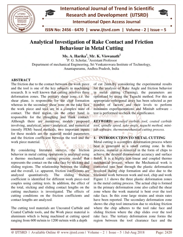
The friction due to the contact between the work piece and the tool is one of the key subjects in machining research. It is well known that cutting involves three deformation zones. The primary shear zone, i.e. the shear plane, is responsible for the chip formation whereas in the secondary shear zone on the rake face the work piece and tool are in a complex state of contact. The third region, on the other hand is responsible for the ploughing and flank contact. Although there are numerous models proposed involving, analytical, semiu00c2u00ac analytical, and numerical mostly FEM based methods, two important inputs for these models are the material model parameters and the friction coefficient between the tool and the work piece material. By considering literature surveys, the friction behavior in metal cutting operations is analyzed using a thermo mechanical cutting process model that represents the contact on the rake face by sticking and sliding regions. The relationship between the sliding and the overall, i.e. apparent, friction coefficients are analyzed quantitatively. The sliding friction coefficient is identified for different work piecetool couples using cutting tests. In addition, the effect of the total, sticking and sliding contact lengths on the cutting mechanics is investigated. The effects of cutting conditions on the friction coefficients and contact lengths are analyzed. The cutting tool materials are Uncoated Carbide and Coated Carbide tools, and the Work piece material is aluminum which is being machined at cutting speed ranging from 600 m min to 1200 m min with a depth of cut 2mm.By considering the experimental results for the analysis of Rake Angle and friction behavior in metal cutting Turning , the parameters are optimized by using the Taguchi method. For this an appropriate orthogonal array has been selected as per number of factors and their levels to perform minimum experimentations and Minitab software test is performed to check the significance. Ms. A. Harika | Mr. K. Viswanath "Analytical Investigation of Rake Contact and Friction Behaviour in Metal Cutting" Published in International Journal of Trend in Scientific Research and Development (ijtsrd), ISSN: 2456-6470, Volume-2 | Issue-5 , August 2018, URL: https://www.ijtsrd.com/papers/ijtsrd18308.pdf Paper URL: http://www.ijtsrd.com/engineering/mechanical-engineering/18308/analytical-investigation-of-rake-contact-and-friction-behaviour-in-metal-cutting/ms-a-harika<br>

E N D
International Research Research and Development (IJTSRD) International Open Access Journal Analytical Investigation of Rake Contact and Friction Behaviour in Metal Cutting Ms. A. Harika1, Mr. K. Viswanath2 P. G. Scholar,2Assistant Professor Department of mechanical Engineering, Sri Venkateswara Institute of Technology, Anantapuramu, Andhra Pradesh, India International Journal of Trend in Scientific Scientific (IJTSRD) International Open Access Journal ISSN No: 2456 ISSN No: 2456 - 6470 | www.ijtsrd.com | Volume 6470 | www.ijtsrd.com | Volume - 2 | Issue – 5 Analytical Investigation of Rake Contact and Behaviour in Metal Cutting Friction Ms. A. 1P. Department of mechanical Engineering, Institute of Technology, Anantapuramu, Andhra Pradesh, India ABSTRACT The friction due to the contact between the work piece and the tool is one of the key subjects in machining research. It is well known that cutting deformation zones. The primary shear zone, i.e. the shear plane, is responsible for the chip formation whereas in the secondary shear zone on the rake face the work piece and tool are in a complex state of contact. The third region, on the o responsible for the ploughing and flank contact. Although there are numerous models proposed involving, analytical, semi¬ analytical, and numerical (mostly FEM) based methods, two important inputs for these models are the material model parame and the friction coefficient between the tool and the work piece material. By considering literature surveys, the friction behavior in metal cutting operations is analyzed using a thermo mechanical cutting process model that represents the contact on the rake face by sticking and sliding regions. The relationship between the sliding and the overall, i.e. apparent, friction coefficients are analyzed quantitatively. coefficient is identified for different work piece couples using cutting tests. In addition, the effect of the total, sticking and sliding contact lengths on the cutting mechanics is investigated. The effects of cutting conditions on the friction coefficients and contact lengths are analyzed. The cutting tool materials are Uncoated Carbide and Coated Carbide tools, and the Work piece material is aluminum which is being machined at cutting speed ranging from 600 m/min to 1200 m/min with a depth ranging from 600 m/min to 1200 m/min with a depth of cut 2mm.By considering the experimental results for the analysis of Rake Angle and friction behavior in metal cutting (Turning), the parameters are optimized by using the Taguchi method. For this an appropriate orthogonal array has been selected as per number of factors and their levels to perform minimum experimentations a test is performed to check the significance. KEYWORD: uncoated carbide tool, coa tool, spindle speed, rake angle, taguchi method, mini tab software, thermo-mechanical cutting process. 1.INTRODUCTIONTO METAL CUTTING Metal cutting is a complex deformation process where heat is generated in a small cutting zone. In this process, material is removed in the form of chips to achieve the desired dimensional accuracy and surface finish. It is a highly non-linear and coupled mechanical process, where the Mechanical work is converted into heat through the plastic deformation involved during chip formation and also due to the frictional work between work and tool, chip and work Figure 1.1 shows the three plastic deformati in the metal cutting process. The actual chip is formed in the primary deformation zone also called the shear zone where the work material is bent over the tool rake face. In this zone large strains and strain rates have been reported. The seconda shows the chip tool interaction due to sticking friction where the chip adheres to the tool rake face and sliding friction where the chip slides over the tool rake face. The tertiary deformation zone forms the region between the tool cl region between the tool clearance face and the The friction due to the contact between the work piece and the tool is one of the key subjects in machining of cut 2mm.By considering the experimental results ake Angle and friction behavior in metal cutting (Turning), the parameters are optimized by using the Taguchi method. For this an appropriate orthogonal array has been selected as per number of factors and their levels to perform minimum experimentations and Minitab software – test is performed to check the significance. involves three deformation zones. The primary shear zone, i.e. the shear plane, is responsible for the chip formation whereas in the secondary shear zone on the rake face the work piece and tool are in a complex state of contact. The third region, on the other hand is responsible for the ploughing and flank contact. Although there are numerous models proposed involving, analytical, semi¬ analytical, and numerical (mostly FEM) based methods, two important inputs for these models are the material model parameters and the friction coefficient between the tool and the uncoated carbide tool, coated carbide rake angle, taguchi method, mini- mechanical cutting process. TO METAL CUTTING Metal cutting is a complex deformation process where heat is generated in a small cutting zone. In this process, material is removed in the form of chips to achieve the desired dimensional accuracy and surface linear and coupled thermo mechanical process, where the Mechanical work is converted into heat through the plastic deformation involved during chip formation and also due to the frictional work between work and tool, chip and work Figure 1.1 shows the three plastic deformation zones in the metal cutting process. The actual chip is formed in the primary deformation zone also called the shear zone where the work material is bent over the tool rake face. In this zone large strains and strain rates have been reported. The secondary deformation zone shows the chip tool interaction due to sticking friction where the chip adheres to the tool rake face and sliding friction where the chip slides over the tool rake face. The tertiary deformation zone forms the By considering literature surveys, the friction behavior in metal cutting operations is analyzed using a thermo mechanical cutting process model that the rake face by sticking and sliding regions. The relationship between the sliding and the overall, i.e. apparent, friction coefficients are analyzed quantitatively. coefficient is identified for different work piece–tool ng cutting tests. In addition, the effect of the total, sticking and sliding contact lengths on the cutting mechanics is investigated. The effects of cutting conditions on the friction coefficients and The The sliding sliding friction friction als are Uncoated Carbide and Coated Carbide tools, and the Work piece material is aluminum which is being machined at cutting speed @ IJTSRD | Available Online @ www.ijtsrd.com @ IJTSRD | Available Online @ www.ijtsrd.com | Volume – 2 | Issue – 5 | Jul-Aug 2018 Aug 2018 Page: 2420
International Journal of Trend in Scientific Research and Development (IJTSRD) ISSN: 2456-6470 machined work surface caused mainly due to the cutting edge roundness or the presence of a built up edge. manufacturing environment. Taguchi’s method is a systematic application of design and analysis of experiments for the purpose of robust designing and improved quality. Taguchi achieves this objective by making the process insensitive to variations in output even though noise is present in the process as described by P-diagram (Figure-2). The process is then said to have become ROBUST (Y. P Tidke et al 2014). The approach to optimization in Taguchi, for feasible and potential combinations of process parameters with parametric settings has manufacturers and designers to implement in real time industrial applications. Taguchi parametric design approach has been utilized in past years for identifying the significant processing parameters and optimizing parametric setting. S. H. Tang et al. (2006) have analyzed thin plate for war page, while doing ANOVA using Taguchi’s L9 orthogonal array. The authors screened out melt temperature, packing time and packing pressure as significant factors while filling time is insignificant towards war page defect. Feng, Chung et al. (2006) examined multiple 3.2 Thermo Mechanical Dual-Zone Model The cutting model which is used in this study is briefly presented. In this model, the contact between the chip and the tool on the rake face is represented by a dual-zone approach. Basically, the contact is divided in to the sticking and a sliding friction region, which was originally proposed by Zorev (see Fig 3.1). In the first region, the contact condition is plastic the attractions for Figure 1: Plastic deformation zones in metal cutting. Machining process such as turning, milling, boring and drilling are among others the most important process for discrete part manufacturing. Researchers have been studying machining processes for more than a century to gain better understanding and develop more advanced manufacturing technology. 2.LITERATURE SURVEY There are numerous models are analytical, semi analytical and numerical methods. Two important input methods for the models are material model parameters and the friction co-efficient between the tool and the work piece material. These two inputs can be considered to be independent of the cutting mechanics as they are related to the mechanical and physical properties of the materials. Identification of the both properties is very critical for accurate modeling of the machining process. The focus of the work is on the friction characteristics. Being a common topic in mechanics, friction has been extensively studied in basic sciences; however machinery researches have also paid special attention to friction due to its importance in cutting process. The early studies on the subject concluded that there is a direct relationship between the share angle and the friction. 3. METHODS AND METHODOLOGY 3.1 Taguchi method A very useful DoE approach namely Taguchi’s Quality function that maximizes the investigated process parameter space through minimal number of experiments. Taguchi’s approach to quality control applies to the entire process of developing and manufacturing a product from initial concept to manufacturing/production in computer integrated Figure2: Stress distribution on the rake face of the tool Due to the high normal pressure exerted on the tool, whereas in these contact regions the contact is elastic which can be represented by the sliding friction. There are two different friction coefficients that are defined on the rake contact. The apparent friction coefficient µa is due to the total cutting forces acting on the rake face. The sliding friction coefficient µ on the other hand, is only due to the forces acting on the @ IJTSRD | Available Online @ www.ijtsrd.com | Volume – 2 | Issue – 5 | Jul-Aug 2018 Page: 2421
International Journal of Trend in Scientific Research and Development (IJTSRD) ISSN: 2456-6470 sliding region on the rake face. The normal pressure distribution on the rake face is needed for the formulation of forces. The following distribution is selected as it issued and verified by several studies. the normal rake angle. The proposed contact model can be used with any primary shear zone model provided that the shear stress at the exit of the shear zone is calculated accurately. For the analysis and predictions conducted in this study, the thermo mechanical primary shear zone model proposed by is used. The main assumption in modeling the primary shear zone is that the shear plane has a constant thickness, and that no plastic deformation occurs before and after the shear plane up to the sticking region on the rake face Where on the rake face from the tool tip, and exponential constant which represents the distribution of the pressure, and is selected as 3 in the current study based on the analysis of the split-tool test results. It can be observed from Fig. 1, that the shear stress on the rake face is equal to the shear yield stress of the material along the sticking region with length . In addition, the shear stress in the sliding region is equal to the product of the sliding friction is the total contact length, x the distance an STICKING CONTACT LENGTH (mm) 0.2 0.4 0.6 0.4 0.6 0.2 0.6 0.2 0.4 CUTTING SPEED (m/min) RAKE ANGLE (deg) JOB NO. 1 2 3 4 5 6 7 8 9 200 200 200 400 400 400 800 800 800 5 10 15 5 10 15 5 10 15 coefficient to the Coulomb friction law. Therefore, the mathematical representation of the shear stress distribution on the rake face can be defined as follows: and the normal stress (P), according CONCLUSION In this thesis, an investigation of the rake contact and friction behaviors in metal cutting operations is performed. The friction behavior in metal cutting operations is analyzed using a thermo mechanical cutting process model that represents the contact on the rake face by sticking and sliding regions. The total contact length increases by the feed rate and decreases by the cutting speed. The apparent friction coefficient strongly depends on the relative length of the sticking and sliding zones, and sliding friction coefficient. It shows that the apparent friction coefficient is always smaller than the sliding friction coefficient. The sticking contact length is strongly affected by the cutting speed. For material tool couples, it is observed that the contact is almost completely sliding at high cutting speeds. For slow and moderate cutting speeds the contact involves both sticking and sliding zones. However, even at slow speeds the contact is mainly in the elastic, i.e. sliding state. For the most practical conditions the sticking contact length is less than 15% of the total contact. The three important outputs of the model is the total contact length relationship between the sliding and sticking friction coefficients. , the sticking length , and the In the above equations, f is the uncut chip thickness, the friction angle, the normal shear angle, the inclination angle, the chip flow angle, and @ IJTSRD | Available Online @ www.ijtsrd.com | Volume – 2 | Issue – 5 | Jul-Aug 2018 Page: 2422
International Journal of Trend in Scientific Research and Development (IJTSRD) ISSN: 2456-6470 3.Feng C. X. (Jack) and Wang X., (2002), “Development of Empirical Models for Surface Roughness Prediction International Journal of Advanced Manufacturing Technology, Volume 20, pp. 348–356 4.Suresh P. V. S., Rao P. V. and Deshmukh S. G., (2002), “A genetic algorithmic approach for optimization of surface roughness prediction model”, International Journal of Machine Tools and Manufacture, Volume 42, pp. 675–680. 5.Lee S. S. and Chen J. C., (2003), “Online surface roughness recognition system using artificial neural networks system in turning operations” International Journal of Advanced Manufacturing Technology, Volume 22, pp. 498–509. 6.Choudhury S. K. and Bartarya G., (2003), “Role of temperature and surface finish in predicting tool wear using neural network and design of experiments”, International Journal of Machine Tools and Manufacture, Volume 43, pp. 747–753. 57 7.Chien W.-T. And Tsai C.-S., (2003), “The investigation on the prediction of tool wear and the determination of optimum cutting conditions in machining 17-4PH stainless steel”, Journal of Materials Processing Technology, Volume 140, pp. 340–345. 8.Kirby E. D., Zhang Z. and Chen J. C., (2004), “Development of An Accelerometer based surface roughness Prediction Operation Using Techniques”, Journal of Industrial Technology, Volume 20, Number 4, pp. 1-2 9.Özel T. and Karpat Y., (2005), “Predictive modelling of surface roughness and tool wear in hard turning using regression and neural networks”, International Journal of Machine Tools and Manufacture, Volume 45, pp. 467–479 The sliding friction coefficient for various material tool couples are identified which can be used for further studies. The main parameter that affects the sliding friction coefficient observed to be the friction speed. However, in some cases the sliding friction coefficient is observed to have a slight dependency on the feed rate which affects the average pressure on the rake face. It is analytically and experimentally shown that the true representation on the friction behavior on the rake face should include the sliding and sticking friction regions. it is observed that the friction model affects the accuracy of the feed force predictions more than the cutting force predictions. Based on the cases considered in this study, it can be concluded that the total and sticking contact lengths are approximately 3-4 and 0-1 times the feed rate, respectly, both decreasing with the cutting speed. Optimization of parameters in turning using MINI TAB software of Taguchi method Mild steel with un coated carbide tool is at optimal value for the parameters. Cutting speed is 400 m/min Rake angle is 5 deg Sliding contact length is 0.6 mm aluminium with coated carbide tool at optimal value for the parameters Cutting speed is 600m/min Rake angle is 5 deg Sliding contact length is 0.2 mm REFERENCES 1.Zhou Q., Hong G. S. and Rahman M., (1995), “A New Tool Life Criterion For Tool Condition Monitoring Using Engineering Application Artificial Intelligence, Volume 8, Number 5, pp. 579-588. 2.Lin W. S., Lee B. Y., Wu C. L., (2001), “Modelling the surface roughness and cutting force for turning”, Journal of Materials Processing Technology, Volume 108, pp. 286-293. in Finish Turning”, System Multiple in Turning Regression a Neural Network”, @ IJTSRD | Available Online @ www.ijtsrd.com | Volume – 2 | Issue – 5 | Jul-Aug 2018 Page: 2423