Download
1 / 4
40 likes | 52 Views
The sheet metal cutting process is a main part of the all industries. Normally the sheet metal cutting machine is manually hand operated one for medium and small scale industries. In our project is "Analysis Of Hydraulic Sheet Cutting Machine And Its Fixture By Using FEA"u009d. Automation in the modern world is inevitable. Any automatic machine aimed at the economical use of man, machine, and material worth the most. The sheet metal cutting machine is used to cut the small size of sheet metal. The machine is portable in size, so easy transportable. The sheet metal cutting machine works with the help of hydraulic cylinder. The piston is connected to the moving cutting tool. It is used to cut the small size of sheet metal. The machine is portable in size, so easy transportable. Ms. Mayuri Kishor Dhande | Mr. Tushar Devidas Garse "Analysis of Hydraulic Sheet Cutting Machine and its Fixture by using FEA" Published in International Journal of Trend in Scientific Research and Development (ijtsrd), ISSN: 2456-6470, Volume-3 | Issue-5 , August 2019, URL: https://www.ijtsrd.com/papers/ijtsrd25315.pdf Paper URL: https://www.ijtsrd.com/engineering/mechanical-engineering/25315/analysis-of-hydraulic-sheet-cutting-machine-and-its-fixture-by-using-fea/ms-mayuri-kishor-dhande<br>

E N D
International Journal of Trend in Scientific Research and Development (IJTSRD) Volume 3 Issue 5, August 2019 Available Online: www.ijtsrd.com e-ISSN: 2456 – 6470 Analysis of Hydraulic Sheet Cutting Machine and its Fixture by using FEA Ms. Mayuri Kishor Dhande1, Mr. Tushar Devidas Garse2 1M.Tech Student, 2Assistant Professor 1,2Department of Mechanical Engineering, JTMCOE, Faizpur, Maharashtra, India How to cite this paper: Ms. Mayuri Kishor Dhande | Mr. Tushar Devidas Garse "Analysis of Hydraulic Sheet Cutting Machine and its Fixture by using FEA" Published in International Journal of Trend in Scientific Research and Development (ijtsrd), ISSN: 2456- 6470, Volume-3 | Issue-5, August 2019, https://doi.org/10.31142/ijtsrd25315 Copyright © 2019 by author(s) and International Journal of Trend in Scientific Research and Development Journal. This is an Open Access article distributed under the terms of the Creative Commons Attribution License (CC (http://creativecommons.org/licenses/by /4.0) The machine is capable of serving as a hydraulic press, sheet metal brake, shear for thin sheet metal, and tubing bender is ideal for use in a home Workshop, where space may be limited.The basic working principle of hydraulic press is depends on the Pascal’s law i.e.” it uses the pressure exerted on fluid used to crush something”. Hydraulic systems are used to transfer energy by converting mechanical energy to fluid energy, and then back to mechanical energy. The principle reason for converting to fluid energy is the convenience of transferring energy to a new location. Hydraulic drives have many advantages over other technologies. The ratio of weight, volume and inertia to available power is significantly electromechanical drives, especially for linear motion. Hydraulic systems are especially suitable for those operations characterized by abrupt loading, frequent stops and starts, reversing and speed variations that cause sharp peak, cyclic and fluctuating power demands. Many device of mechanical are based on hydraulic power. Hydraulic device uses principles of fluid static and fluid kinematics are used for either storing the hydraulic energy or then transmitting when needed or maintaining the hydraulic energy several times and transmitting the same. In all such machines, power is transmitted with the help of a fluid, which may be water or oil. Our mechanism is used in industrial fitting and maintaining department, in automobile garage or in ABSTRACT The sheet metal cutting process is a main part of the all industries. Normally the sheet metal cutting machine is manually hand operated one for medium and small scale industries. In our project is “Analysis Of Hydraulic Sheet Cutting Machine And Its Fixture By Using FEA”. Automation in the modern world is inevitable. Any automatic machine aimed at the economical use of man, machine, and material worth the most. The sheet metal cutting machine is used to cut the small size of sheet metal. The machine is portable in size, so easy transportable. The sheet metal cutting machine works with the help of hydraulic cylinder. The piston is connected to the moving cutting tool. It is used to cut the small size of sheet metal. The machine is portable in size, so easy transportable. KEYWORDS: Hydraulics, hydraulic jack, control valves, Die, springs I. INTRODUCTION The sheet metal cutting process is a main part of the all industries. Normally the sheet metal cutting machine is manually hand operated one for medium and small scale industries. The metal shit cutting by hand hacksaw is hardworking and time consuming. The labour charges also increases. Hence the process is uneconomical. In our project we are making hydraulically powerised machine which is used for cutting, bending , pressing operations. As a development part it will be of a small capacity and simple but function properly. The sheet metal of maximum 0 to 3 mm width can cut easily and 20 to 30mm length of sheet . So every time the bar has to feed up to stopper manually is the effort and extra work to operator. industrial workshop. Our project is used for reducing manufacturing cost and saving time and also to reduce maintaining cost or a manufacturing cost. Here we manufacture a lightweight & easy to handle machine so that you can carry anywhere into the shop. In this project the force from the press is used to do a particular operation. This is done by two main parts die and punch. DIE: Die is the lower part of the press tool. It is claimed on to the bolster plate of the press. It remains stationary during the operation. The die has a capacity suitable or respective profile to receive the punch. The cavity may or without a clearance. PUNCH: Punch is the upper part of the press tool. It is attached to the lower end of the ram of the press. It slides with the press ram during the operation and is forced in the die cavity. The die and punch must be in perfect alignment for proper operation. Materials used for punch and die, High speed steel Starlit or cemented carbide. CLEARANCE: It is the space between the mating members of a die set. Proper clearance between cutting edges enables the fractures to meet and the fractured position of the shared edge has a clear appearance. For optimum finish of cut edge, proper clearance is necessary and is a function of the kind thickness and temper of the work material. IJTSRD25315 pp.576-579, BY 4.0) lower than in @ IJTSRD | Unique Paper ID – IJTSRD25315 | Volume – 3 | Issue – 5 | July - August 2019 Page 576
International Journal of Trend in Scientific Research and Development (IJTSRD) @ www.ijtsrd.com eISSN: 2456-6470 PUNCH CLEARANCE: For complete clearance of the metal is necessary that the punch should enter into the cavity of the die block. The space between each face of the die block and the corresponding face of the punch block and the corresponding face on the die is called punch clearance. The amount of clearance depends upon the type of the material and the thickness of the blank being should share. The usual value of the punch clearance is 5% to 8% of the plate thickness. If the punch clearance is less than the appropriate clearance, the fracture fails to meet at the center. If the punch clearance is too great, then the punch and die will operate like a drawing die. DIE CLEARANCE: The operating of the die is slightly conical extending from the cutting edge. The metal is backed off all around the cutting edge to provide relief. The clearance is usually ¼ degree which may be more or less according to the type of material being punched. The die clearance is also serves to provide relief to punched metal to fall through without getting struck up in the die cavity. ANGULAR CLEARANCE: This is defined as the clearance below the straight portion of die surface introduced for the purpose of enabling the blank or the slug (piercing operation) to clear the die. Angular clearance is usually ground from ¼ degree to 4 degree per side depending mainly on stock thickness and the frequency of sharpening. LEVERS: A lever is a rigid rod or bar capable of turning about a fixed point called fulcrum. Lever is used as a machine to apply or lift a load with less effort. The force applied by the lever may be parallel or inclined to one another. PRINCIPLE OF LEVERS: The points A and B through which the load and effort is applied are known as load and effort point respectively. F is the fulcrum about which the lever is capable of turning. The perpendicular distance between the load point and the fulcrum is known as the load arm. The perpendicular distance between the effort point and the fulcrum is called as effort arm. TYPES OF LEVER: A.First type lever: The fulcrum is in between the load and the effort arm. Effort arm is greater than load arm. Mechanical advantage is more than one. B.Second type lever: The load is in between the fulcrum and the effort. The effort arm is more than load arm. So mechanical advantage is more than one. C.Third type lever: The effort arm is in between the fulcrum and the effort arm. The effort is less than load arm. Mechanical advantages are less than one. II. LITRATURE REVIEW This is an era of automation where it is broadly defined as replacement of manual effort by mechanical power in all degrees of automation. The operation remains an essential part of the system although with changing demands on physical input as the degree of mechanization is increased. Automation can be achieved through computers, hydraulics, pneumatics, robotics, etc., of these sources, pneumatics form an attractive medium for low cost automation. K. Sainath, Mohdsalahuddin MohdjibranBaig, MdAzam Ali Farooky,Mohammes Siddique Ahmed, MohdRiyaz Uddin, Faraz Ur Rehman Azhar,Md Shaffi [1] explains that hydraulic jack depends on force generated by pressure. A jack is device which uses to lift heavy loads by force. A jack can be categorized by the type of force which they employ : mechanical or hydraulic jack. Mechanical jack such as car jack , house jack and hydraulic jack such as bottle jack or floor jack. Chinthakindi Vinod, P. Chandra Kumar, CH. Sharath Reddy [2] explains that in present world automation is the need of time in order to reduce the human effort. Hydraulic machine have different type of uses like pipe bending, sheet bending operations and many more. pipes and sheets are used in various fabrication works and architectural work . To bend these pipes and sheets in various is very hard by manually. Using a particular machine to develop the sheets and pipes will be useful. Designing of machine is done in software CATIA and analysis of work piece are done to find strain, stress, deformation with the help of ANSYS software. Bhushan v. Golechha, Prashant S. Kulkarni [3] explains the power press machine working. It is a cheap less manufacturing process. The of this process to reduce the cost and weight of pneumatic press without reducing the quality of output. For the analysis of project ANSYS software used. Power press is useful for large quantities of articles quickly, accurately and economically. there are three types of power press : mechanical, hydraulic and pneumatic . Some features of this press are common. Mustafa Telwala, Anand Parikh, Vaja Hitesh, Hardikbhai Dabhi, Rajdipsingh G.Vaghela, Hardik N. Chauhan (2015) [4] explains that power press working machine is a cheap less manufacturing process. Press has a bed, frame which exerts force upon work material through special tool. For the analysis of force and load solid works software has been used. The main aim of the frame is to withstand the force developed by ram. C-type frame is mostly used frame. Malachy Sumaila and Akii Okonigbon Akaehomen Ibhadode (2011) [5] explains that 30 ton hydraulic press was constructed, designed and tested using available sourced materials. The main advantage of hydraulic presses over that they provide more positive response to changes in input pressure force. The hydraulic press is an valuable equipment in the workshop and laboratories. All workshop in Nigeria al such machines are imported into the country. Mohamad M. Saleh B. Engg. , M. Engg. (2012) [6] explains that systematic study and performance of 150 ton hydraulic press machine. The study gives the experimental and theoretical model of machine to establish design analysis at minimum time and lower cost. This hydraulic press machine used in large capacity of industries. Ti is useful in many of operations at low cost and low maintenance. III. OBJECTIVE OF STUDY The main objective of this project is to analyze the study of hydraulic press operations like cutting, bending, pressing, punching. Also perform job holding process effectively with less human efforts by using machine with hydraulic power. This machine used in small scale and medium scale industries. IV. PROBLEM STATEMENT Now a days there are lots of cutting machines available in market for cutting, bending, pressing operations but due to high cost and high maintenance, for small scale industries @ IJTSRD | Unique Paper ID – IJTSRD25315 | Volume – 3 | Issue – 5 | July - August 2019 Page 577
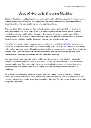
International Journal of Trend in Scientific Research and Development (IJTSRD) @ www.ijtsrd.com eISSN: 2456-6470 this machines are not ideal. Also we have found that during the research there are difficulties while maintaining this machines . But problem lies in the actual process of forming these shapes from sheets of metals. various large and heavy machinery are required and are also available in manufacturing sector for this purpose. But for a small scale industry these heavy machinery are not ideal due to high cost and floor space as well as expertise needed to operate these machines. also considering the growing need of automation in the industries these robust and large machines can not fit in the to serve the purpose of automation. To overcome this problem research has been conducted to find a solution on how to design hydraulic cutting machine serving all the above problems and satisfy the need of low cost small size, medium skill requirement and which is fit for future needs and that is what we have tried to achieve in this project. V. METHODOLOGY In this study we are going to analyze the hydraulic press operations like cutting, bending, pressing. Every press has got certain basic units. Base is the lower part of the press frame. A sheet metal plate is placed on the top of the bed. A die is fitted on the top of the metal plate. The frame has got guide ways for the sliding movement of the ram. The punch is fitted at the bottom of the ram. The die and punch are correctly aligned. The work piece is in the form of sheet metal. It is fed over the die. When the ram comes down, the punch presses the sheet metal. The required operation is carried out. As said earlier the force from the press is used to do a particular operation. This is done by two main parts die and punch. Mechanization is broadly defined as the replacement of manual effort by mechanical power. Hydraulic is an attractive medium for low cost mechanization particularly for sequential (or) repetitive operations. Many factories and plants already have compressed oil system, which is capable of providing the power (or) energy requirements and the control system (although equally hydraulic control systems may be economic and can be advantageously applied to other forms of power). The main advantage of an all hydraulic system are usually economic and simplicity the latter reducing maintenance to a low level. It can also have outstanding advantages in terms of safety. SELECTION OF HYDRAULICS Mechanization is broadly defined as the replacement of manual effort by mechanical power. Hydraulic is an attractive medium for low cost mechanization particularly for sequential (or) repetitive operations. Many factories and plants already have compressed oil system, which is capable of providing the power (or) energy requirements and the control system (although equally hydraulic control systems may be economic and can be advantageously applied to other forms of power). The main advantage of an all hydraulic system are usually economic and simplicity the latter reducing maintenance to a low level. It can also have outstanding advantages in terms of safety. PRODUCTION OF COMPRESSED OIL Hydraulic systems operate on a supply of compressed oil, which must be made available. In sufficient quantity and at a pressure to suit the capacity of the system. When hydraulic system is being adopted for the first time, however it wills indeed the necessary to deal with the question of compressed oil supply. The key part of any facility for supply of compressed oil is by means using reciprocating compressor. A compressor is a machine that takes in oil, gas at a certain pressure and delivered the oil at a high pressure. Compressor capacity is the actual quantity of oil compressed and delivered and the volume expressed is that of the oil at intake conditions namely at atmosphere pressure and normal ambient temperature. Clean condition of the suction oil is one of the factors, which decides the life of a compressor. Hydraulic systems possess numerous advantages over other systems of power operation. They are light in weight; they are simple and extremely reliable, requiring a minimum of attention and maintenance. Hydraulic controls are sensitive, and afford precise controllability. Because of the low inertia of moving parts, they start and stop in complete obedience to the desires of the operator, and their operation is positive. Hydraulic systems are self-lubricated; consequently there is little wear or corrosion. Their operation is not apt to be interrupted by salt spray or water. Finally, hydraulic units are relatively quiet in operation, an important consideration when detection by the enemy must be prevented. WORKING PROCEDURE: Every press has got certain basic units. Base is the lower part of the press frame. A sheet metal plate is placed on the top of the bed. A die is fitted on the top of the metal plate. The frame has got guide ways for the sliding movement of the ram. The punch is fitted at the bottom of the ram. The die and punch are correctly aligned. The work piece is in the form of sheet metal. When the ram comes down, the punch presses the sheet metal. The cam shaft movement is up and down motion due to cam mechanism. The cam shaft of other end is connected to the hydraulic pump handle. The hydraulic handle moves up and down according to the movement of the cam shaft. So the pressurized oil goes to the hydraulic cylinder and moves the piston upward, so that the pressure is applied to the cutting tool top to ground. The following figures of project are drawn into ANSYS software Fig. 1 Bottom plate @ IJTSRD | Unique Paper ID – IJTSRD25315 | Volume – 3 | Issue – 5 | July - August 2019 Page 578
International Journal of Trend in Scientific Research and Development (IJTSRD) @ www.ijtsrd.com eISSN: 2456-6470 The above fig. are of von misses stress of bottom plate and upper plate. VI. CONCLUSION In this paper from the above discussion it is concluded that developed machine can overcome the criterion of cutting material up to thickness 3mm-5mm with width of 25mm. So it saves energy, reduces tonnage capacity of machine reduces the cost of operation as well as human efforts. This assembled machine do not required skilled operator. It is concluded at such kind of machine are very much of importance in industries for sharing purpose also with this machine we can remove press fit assemblies of shafts and gear and for light pressing work. ACKNOWLEDGEMENT I am deeply expressing my sincere gratitude to my project guide Prof. T. D. Garse who always supported and guided me with valuable guidance. I express my immense pleasure and thankfulness to all faculty members of the Department of Mechanical Engineering of J. T. M. C. O. E. , Faizpur VII. REFERENCES [1]K. Sainath, Mohdsalahuddin MohdjibranBaig, MdAzam Ali Farooky,Mohammes Siddique Ahmed, MohdRiyaz Uddin, Faraz Ur Rehman Azhar,Md Shaffi (2014) IOSR Journal of Engineering (IOSRJEN), ISSN(e): 2250-3021, ISSN (P): 2278-8719, Vol. 04, Issue 07 (July. 2014), PP 15-28 “DESIGN OF MECHANICAL HYDRAULIC JACK”. Fig. 2 Middle Plate Fig 3 Supporting Rod [2]Chinthakindi Vinod, P. Chandra Kumar, CH. Sharath Reddy (2017) International Journal of Engineering Technology Science www.ijetsr.com , ISSN 2294-3386 Volume 4. “Design and Dynamic Analysis of Hydraulic Press Machine for Sheet and Pipe bending Operations”. and Research IJETSR [3]Bhushan v. Golechha, Prashant S. Kulkarni (2017) , IJARIIE-ISSN(O)-2395-4396, vol-3,” Design, Analysis And Optimization Of 10 Ton Pneumatic Machine”. Fig. 4 Upper Plate [4]Mustafa Telwala, Anand Parikh, Vaja Hitesh, Hardikbhai Dabhi, Rajdipsingh G.Vaghela, Hardik N. Chauhan (2015). “A Review On Cost Optimization Of Power Press By Analysis Of C-Frame Using Solid Works”. [5]Malachy Sumaila and Akii Okonigbon Akaehomen Ibhadode (2011), Mechanical Engineering Department, Federal University Of Technology, Nigeria. “Design And Manufacture Of A 30-Ton Hydraulic Press”. [6]Mohamad M. Saleh B. Engg. , M. Engg. (2012) thesis of “Design Study Of A Heavy Duty Hydraulic Machine Using Finite Element Technique” submitted to Dublin City University. Fig.5 Equivalent von-misses stress [7]Asim M. Kamate (IJITR) International Journal Of Innovative Technology And Research Volume No. 4, Issue No. 1, December – January7 2016, 2560-2563. “Design, Analysis And Development Of 20-Ton Hydraulic Press”. [8]Book of “Design For Manufacturing And Assembly” , S.S Rao, Engineering Optimization, Newage Publication. Fig. 6 Equivalent von-misses stress of upper plate @ IJTSRD | Unique Paper ID – IJTSRD25315 | Volume – 3 | Issue – 5 | July - August 2019 Page 579