Download
1 / 3
30 likes | 51 Views
In recent years voltage and current harmonics are become serious problem in transmission and distribution system. To eliminate these voltage and current harmonics and to achieve clean grids, AAF are been used. The existing AAF technology requires a higher dc link voltage to achieve the THD requirement therefore this paper presents an Advanced Active Filter AAF for IGBT and LCL network in order to maintain voltage balance among dc link. This method is well capable of balancing charging and discharging of dc link voltage without increasing circuit complexity. This modulation technique is very effective in terms of voltage balancing as well as for maintaining voltage output THD at low level. The proposed system is implemented in Simulink platform of MATLAB software and performance shows its effectiveness over conventional IGBT used for inverter Tamil Selvan P | Vinothkumar K | Sugumar V "Advanced Active Filter (AAF) with Reduced DC Link Voltage" Published in International Journal of Trend in Scientific Research and Development (ijtsrd), ISSN: 2456-6470, Volume-3 | Issue-3 , April 2019, URL: https://www.ijtsrd.com/papers/ijtsrd21764.pdf Paper URL: https://www.ijtsrd.com/engineering/electronics-and-communication-engineering/21764/advanced-active-filter-aaf-with-reduced-dc-link-voltage/tamil-selvan-p<br>

E N D
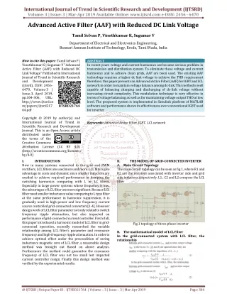
International Journal of Trend in Scientific Research and Development (IJTSRD) Volume: 3 | Issue: 3 | Mar-Apr 2019 Available Online: www.ijtsrd.com e-ISSN: 2456 - 6470 Advanced Active Filter (AAF) with Reduced DC Link Voltage Tamil Selvan P, Vinothkumar K, Sugumar V Department of Electrical and Electronics Engineering, Bannari Amman Institute of Technology, Erode, Tamil Nadu, India How to cite this paper: Tamil Selvan P | Vinothkumar K | Sugumar V "Advanced Active Filter (AAF) with Reduced DC Link Voltage" Published in International Journal of Trend in Scientific Research and Development (ijtsrd), ISSN: 2456- 6470, Volume-3 | Issue-3, April 2019, pp.304-306, URL: http://www.ijtsrd.co m/papers/ijtsrd217 64.pdf Copyright © 2019 by author(s) and International Journal of Trend in Scientific Research and Development Journal. This is an Open Access article distributed under the terms of the Creative Commons Attribution License (CC BY 4.0) (http://creativecommons.org/licenses/ by/4.0) I. INTRODUCTION Now in many systems connected to the grid and PWM rectifiers, LCL filters are used more and more. LCL filters give advantage in costs and dynamic since smaller inductors are needed to achieve required performance in damping the switching harmonics comparing with L or LC filters. Especially in large power systems whose frequency is low, the advantages of LCL filter are more significant. Because LCL filter need smaller inductance value comparing to L type filter at the same performance in harmonic suppression, it is gradually used in high-power and low frequency current source controlled grid-connected converters[1-4]. However design work of LCL filter parameter not only related to switch frequency ripple attenuation, but also impacted on performance of grid-connected current controller. First of all, this paper introduced a harmonic model of LCL filter in grid- connected operation, secondly researched the variable relationship among LCL filter’s parameter and resonance frequency and high-frequency ripple attenuation. In order to achieve optimal effect under the precondition of saving inductance magnetic core of LCL filter, a reasonable design method was brought out Based on above analysis. Furthermore the method could guarantee the resonance frequency of LCL filter was not too small lest impacted current controller resign. Finally this design method was verified by the experimental results. ABSTRACT In recent years voltage and current harmonics are become serious problem in transmission and distribution system. To eliminate these voltage and current harmonics and to achieve clean grids, AAF are been used. The existing AAF technology requires a higher dc link voltage to achieve the THD requirement therefore; this paper presents an Advanced Active Filter (AAF) for IGBT and LCL network in order to maintain voltage balance among dc-link. This method is well capable of balancing charging and discharging of dc-link voltage without increasing circuit complexity. This modulation technique is very effective in terms of voltage balancing as well as for maintaining voltage output THD at low level. The proposed system is implemented in Simulink platform of MATLAB software and performance shows its effectiveness over conventional IGBT used for inverter Keywords: Advanced Active Filter, IGBT, LCL network IJTSRD21764 II. A.Main Circuit Topology The main circuit topology can be seen as fig.1, where R1 and R2 are the resistors associated with inverter side and grid side inductors respectively. L1 , C2 and L2 compose the LCL filter THE MODEL OF GRID-CONNECTED INVERTER Fig.1 topology of three-phase inverter B.The mathematical model of LCL Filter In the grid-connected system with LCL filter, the relationship @ IJTSRD | Unique Paper ID - IJTSRD21764 | Volume – 3 | Issue – 3 | Mar-Apr 2019 Page: 304
International Journal of Trend in Scientific Research and Development (IJTSRD) @ www.ijtsrd.com eISSN: 2456-6470 III. THE CHARACTERISTIC ANALYSIS OF LCL FILTER Fig 2.2 Input side of three-phase rectifier without filter B.THREE PHASE RECTIFIER WITH FILTER IV. To verify the proposed design method, a three-phase experimental platform based on DSP TMS320LF2407 is established. Based on 20% ripple wave RMS strict condition, the inductance value of L1 can be calculated. Then in the paper L1 = 5.5mH, L2 = 1.0mH, and C2=20 µf. Under the two- current-loop control, the system is connected to the grid safely. The waveforms of the grid-connected current with the designed LCL filter. The harmonic analysis of grid-connected current. The harmonic above resonant frequency was suppressed A.THREE PHASE RECTIFIER WITHOUT FILTER EXPERIMENTAL RESULT Fig.3 three-phase rectifier with filter Fig.2 three-phase rectifier without filter Fig3.1THD value for three-phase rectifier with filter Fig2.1 THD value for three-phase rectifier without filter Fig3.2 output of three-phase rectifier with filter @ IJTSRD | Unique Paper ID - IJTSRD21764 | Volume – 3 | Issue – 3 | Mar-Apr 2019 Page: 305
International Journal of Trend in Scientific Research and Development (IJTSRD) @ www.ijtsrd.com eISSN: 2456-6470 V. In this paper, a parameter-design method is proposed for a LCL filter used in a three-phase grid-connected inverter system. The practicality of this method is practicability and validity. Experimental results proved the correctness of the adopted parameter-design theory analysis and feasibility of the proposed design method. The adoption of filter-capacitor- current inner loop can damp the resonance of LCL filter as analyzed. The design method made the tuning procedure easier and the system harmonic suppression performance good. VI. References [1]Teodorescu, R., Blaabjerg, F., Borup, U. et al. A New Control Structure for Grid- Connected LCL PV Inverters with Zero Steady-State Error and Selective Harmonic Compensation. Applied Power Electronics Conference and Exposition. 2004. APEC’04. Nineteenth Annual IEEE Vol. 1, 2004 Page(s):580-581 CONCLUSIONS inverters with a LCL filter[C]. IEEE 21th Annual, 2006:1067~1073 [5]Liserre,M., Blaabjerg,F., Hansen, S. Design and control of an LCL-filter based three-phase active rectifier[C]. Thirty-Sixth IAS Annual Meeting Conference Record of the 2001 IEEE, 2001, 1:299-307 [6]Hamid R, Hadi Saghafi. Basic Criteria in Designing LCL Filter for Grid Connected Converters. IEEE ISIE July.2006,pp.1996-2000. [7]Michael Lindgren, Jan Svensson. Control of a voltage- source converter connected to the grid through an LCL- filter-application to active filtering[C]. IEEE 29th Annual Volume, 1998, 1:229-235 [8]Magueed,F.A., Svensson, J. Control of VSC connected to the grid through LCL -filter to achieve balanced currents. Fourtieth[C]. IAS Annual Meeting Conference Record, 2005, 1:572-578 [2]Twining,E., Holmes,D.G. Grid current regulation of a three-phase voltage source inverter with an LCL input filter[J]. IEEE Trans. On Power Electronics. 2003, 18(5): 888-895 [9]Fei Liu, Shanxu Duan, Pengwei Xu, Guoqiang Chen and Fangrui Liu, “Design and Control of Three-Phase PV Grid Connected Converter with LCL Filter,” IECON’07, Nov. 2007, pp. 1656-1661. [3]Magueed,F.A., Svensson, J. Control of VSC connected to the grid through LCL-filter to achieve balanced currents[C]. Fourtieth IAS Annual Meeting Conference Record, 2005, 1:572-578 [10]Papavasiliou, S.A. Papathanassiou, S.N. Manias and G. Demetriadis, “Current Control of a Voltage Source Inverter Connected to the Grid via LCL Filter,” PESC’07, Jun. 2007, pp. 2379-2384. [4]Shen Guoqiao, Xu Dehong, Xi Danji et al. An improved control strategy for grid-connected voltage source @ IJTSRD | Unique Paper ID - IJTSRD21764 | Volume – 3 | Issue – 3 | Mar-Apr 2019 Page: 306