Download
1 / 3
30 likes | 52 Views
This paper focuses on the designing, simulation and fabrication of brake disc and a constant speed two stage reduction gearbox for an All Terrain Vehicle ATV . In our paper, we have presented an efficient gearbox and brake disc which is lightweight and long lasting. The drive train consists of Continuous Variable Transmission CVT and a constant mesh two stage reduction gearbox. The gearbox and disc brake were modeled on SOLIDWORKS version 2018 and analyzed on ANSYS mechanical workbench version 2016 and the result were found to be satisfactory. Shashwat Kulshreshtha | Shantanu Tiwari | Naman Varshney | Shikhar Verma | Mayank Kushwaha "A Review: Design of Effective Braking and Efficient Transmission System" Published in International Journal of Trend in Scientific Research and Development (ijtsrd), ISSN: 2456-6470, Volume-4 | Issue-4 , June 2020, URL: https://www.ijtsrd.com/papers/ijtsrd30969.pdf Paper Url :https://www.ijtsrd.com/engineering/mechanical-engineering/30969/a-review-design-of-effective-braking-and-efficient-transmission-system/shashwat-kulshreshtha<br>

E N D
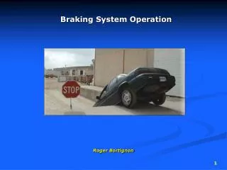
International Journal of Trend in Scientific Research and Development (IJTSRD) Volume 4 Issue 4, June 2020 Available Online: www.ijtsrd.com e-ISSN: 2456 – 6470 A Review: Design of Effective Braking and Efficient Transmission System Shashwat Kulshreshtha, Shantanu Tiwari, Naman Varshney, Shikhar Verma, Mayank Kushwaha Department of Mechanical Engineering, ABES Engineering College, Ghaziabad, Uttar Pradesh, India ABSTRACT This paper focuses on the designing, simulation and fabrication of brake disc and a constant speed two-stage reduction gearbox for an All-Terrain Vehicle (ATV). In our paper, we have presented an efficient gearbox and brake disc which is lightweight and long lasting. The drive train consists of Continuous Variable Transmission (CVT) and a constant mesh two-stage reduction gearbox. The gearbox and disc brake were modeled on SOLIDWORKS version 2018 and analyzed on ANSYS mechanical workbench version 2016 and the result were found to be satisfactory. KEYWORDS: ATV, CVT, efficient gearbox How to cite this paper: Shashwat Kulshreshtha | Shantanu Tiwari | Naman Varshney | Shikhar Verma | Mayank Kushwaha "A Review: Design of Effective Braking and Efficient Transmission System" Published in International Journal of Trend in Scientific Research and Development (ijtsrd), ISSN: 2456- 6470, Volume-4 | Issue-4, June 2020, pp.337-339, www.ijtsrd.com/papers/ijtsrd30969.pdf Copyright © 2020 by author(s) and International Journal of Trend in Scientific Research and Development Journal. This is an Open Access article distributed under the terms of the Creative Commons Attribution License (CC (http://creativecommons.org/licenses/by /4.0) IJTSRD30969 URL: BY 4.0) INTRODUCTION For an ATV, transmission and braking are two major systems/parameters used to provide control to the performance of a vehicle. The main operation of the braking system is to slash the speed for safe operation of a vehicle. It works on the principle of conversion of kinetic energy into heat energy with the help of frictional force. The transmission system is used to transmit the power supplied by the engine to the wheels. Using the transmission system, we can vary the torque and speed as per the vehicle requirements. Both systems should be effective and efficient. Before designing of braking and transmission components, a literature review of various related research papers has been done in which the following points are noted, Deekshith (2017) showed that at present time usually Cast Iron, Reinforced Carbon–Carbon or Ceramic matrix composites etc. are commercially used materials for disc brake rotor. He chose Gray Cast Iron and Stainless Steel for analysis. Nand Mangukia (2018) presented the design a brake pedal having brake pedal ratio of more than 5:1. It is always suggested that in manual braking system (with no power booster) this ratio should not be greater than 5. To avoid the hindrance to driver’s leg the length of brake pedal should not be too long or too short. The brake pedal ratio should be such that the driver would not feel fatigue while braking. Dr. V. K. Saini (2017) discussed the effect of the location of the center of gravity on dynamic performances, like maximum tilting angle and maximum acceleration. These dynamic parameters depend only upon the weight transfer, and are completely independent of the engine performance and specification. Braking System The main objective of thispaper is to reduce the overall weight of braking system of an ATV without compromising its performance. For designing parts, the selection of material is the primary objective. The first part which is needed to be designed is a disc rotor, the material for disc rotor is generally taken as Gray Cast Iron, Stainless Steel of different grades like SS 409, SS 410 and SS 420. [1] The material selected for the disc rotor is SS410 due to its physical properties and availability. The priority while designing a component is calculation of different forces acting on that component under static and dynamic condition. Dynamic load transfer takes place when driver applies the brake which depends on the weight of the vehicle(W), coefficient of friction between tires and road(μr), distance of CG from axle(a), height of CG from ground(h), and wheelbase of the vehicle(L). The formula for weight transfer for front axle is [2]: ??= ? × (? + ??.ℎ) × cos? ? ??= ? × (?− ?− ??.ℎ) × cos? ? @ IJTSRD | Unique Paper ID – IJTSRD30969 | Volume – 4 | Issue – 4 | May-June 2020 Page 337
International Journal of Trend in Scientific Research and Development (IJTSRD) @ www.ijtsrd.com eISSN: 2456-6470 From these formulae, forces on front and rear axle is calculated and by multiplying it with the wheel radius the torque required on each wheel can be calculated easily. By multiplying that torque with the rotor radius, we can get the clamping force acting on the rotor. Dividing that clamping force with the area of piston we can get the pressure that is required to be generated in the master cylinder.[2] After designing the rotor prototype, it is necessary to do its simulation and Finite Element Analysis (FEA) on software like SolidWorks and ANSYS. For doing static simulation the mounting points of disc rotors are fixed and calculated torque should be applied on the brake pad area. Radial force can be determined as the product of calculated torque and rotor radius. The force applied by the caliper on the rotor is called clamping force that can be calculated by dividing the radial force on rotor by two times of coefficient of friction between rotors and brake pads. Further dividing this force by the surface area of piston we can get pressure which will act on rotor. The same pressure will be applied on rotor. [1][3] Thermal simulation of the disc rotor is also necessary because during breaking the kinetic energy of the vehicle transforms into heat energy and it will result in heating of the disc rotor. This might soften the material and will obviously lead to the deformation on the application of clamping forces. For thermal simulation, we have to take the convection coefficient of material, heat power generated per unit area and initial temperature of the rotor which will be equal to atmospheric temperature. After completion of thermal simulation, its result must be included in static simulation for better results. [1][3] Another component whose weight optimization can be done is brake pedal. Brake pedal transmits the force applied by the driver’s foot to the master cylinder to create pressure inside it. Pedal ratios are defined in brake pedals which enlarge the force applied by the driver accordingly. The material that can be considered for its fabrication is AISI 1018 or Al 7075-T6. The availability of AISI 1018 is easy and it is not as expensive as Al 7075-T6, therefore it is taken into consideration. For its simulation, the pivot point of the pedal is kept fixed and force is applied to the footrest of pedal. Topology study should be performed for removal of extra material and make the pedal lightweight. [4] TransmissionSystem The approachincludes designing all the components necessary for a drivetrain. These components include the driveshaft, spur gears, gearbox, and the appropriate mounts. The transmission of the vehicle decides the numerous attributes of the vehicle such as maximum achievable speed, acceleration by which it can drive the vehicle power at the wheels to lug the load. All these attributes depend on the tractive effort of the vehicle which is the minimum force available to the wheels to keep the vehicle moving. This tractive effort also depends on the weight ratio of the vehicle but major assumption while calculating it is the whole weight at CG rather than the axles of the vehicle. Requirement of the tractive effort to uphill the vehicle on the gradient of 35 degree is calculated by the following equation [6]: ? = ????? + ?? Where F= Tractive force, ? = gradient, ?? = Rolling resistance Driver’s effort or better ride performance is one of the most important attributes of any vehicle. One of the methods to achieve this is by using continuously variable transmission. A CVT offers a continuum of gear ratios between the required or given limits, which therefore enhances the fuel cutback and dynamic performance of a vehicle by better matching the engine control conditions to the variable driving outline. The paper also reviews the variation of CVT ratios with the engine so called powerhouse rpm. Our transmission system utilizes a continuously variable transmission device (CVT). This CVT is opted because of the light weight, lower price compared to OEM and ease in availability compared to others. It provides a maximum ratio of 3:1 and a minimum ratio of 0.79:1. The maximum reduction of CVT is 3:1 so gear ratio of gearbox must be 7.54:1 for optimum torque. We can also obtain a CVT ratio at a particular rpm with the help of below-mentioned formula, this equation helps in precise calculation for our acceleration and velocity [6]: 3 − (2.5 × (???−800)) 2800 Considering the minimum available volume to accommodate gear assembly, a two-stage constant speed reduction gearbox is used. The main components of these equations include material strength, pressure angle, gear reduction ratio, pitch, face width, and the number of teeth on each gear. The gearsare made of EN 8 because of its higher UTS, high yield strength and sufficient hardness to resist indentation. The reduction ratio in the first stage is 2.68:1 and in the second stage is 2.809:1. In an event of Drawbar pull, ATV in consideration is required to pull a specific heavy load vehicle, to a certain distance in order to successfully calculate the potential value of torque needed by the vehicle to complete this task with no repercussions or strains. Thus, with the help of this equation, we can validate our requirement of torque as per this event: [7] where, LL=distance between hitch point on the sled to the center of mass of the movable sledge weight LT=length from the hitch point on the sledge to the centerline of the sledge axle LS= the length from the hitch point on the sledge to the center of mass on the sledge LN= the length from the hitch point on the sledge to the centerline of the support plate @ IJTSRD | Unique Paper ID – IJTSRD30969 | Volume – 4 | Issue – 4 | May-June 2020 Page 338
International Journal of Trend in Scientific Research and Development (IJTSRD) @ www.ijtsrd.com eISSN: 2456-6470 [2]Vivek Singh Negi, Nayan Deshmukh and Amit Deshpande, “Design of Braking System of BAJA Vehicle”, International Journal of Advance Engineering and Research Development, Volume 4, Issue 11, November - 2017 [3]Deekshith, Udaya Kiran, kumar, “Design, Analysis and Manufacturing of Disc Brake Rotor”, International Journal Of Engineering Research And Development, Volume 13, Issue 11 (November 2017). [8] [4]Nand Mangukia and Nandish Mangukia, “Design and Fabrication of Brake Pedal for All Terrain Vehicle”, International Journal of Engineering Research and Development, Volume 6, Issue 2, 2018. Conclusion: The designed rotor disc is heavy as they are common for most vehicles, here we have worked on the weight optimization of disc rotors. Usually in ATVs, CVTs are used which are not tuned according to the engine rpm, so after careful calculations and analysis we have select most effectively gear ratio of 7.54:1 with CVT which provide infinite gear ratio between 3:1 at varying speed and used the discs that are most attended to our purpose. References: [1]M. A. Maleque, S. Dyuti and M. M. Rahman, “Material Selection Method in Design of Automotive Brake Disc”, Proceedings of the World Congress on Engineering 2010 Vol III WCE 2010, June 30 - July 2, 2010, London, U. K. [5]Gillespie, Thomas, Fundamentals of Vehicle Dynamics, SAE International, 1992. [6]Page no. 5, SAE Mini Baja Drivetrain By: Abdulrahman Almuflih, Andrew Perryman, Caizhi Ming, Zan Zhu, Ruoheng Pan, Department of Mechanical Engineering Northern Arizona University Flagstaff, AZ 86011 [2013] [7]V. B. Bhandari “Design of Machine Elements”, Tata McGraw Hill Publication, Third Edition 2010, p.p. 330 - 348, 646 – 700 [8]Page no. 19, Design of an SAE BAJA racing Off Road Vehicle Power train by Eric T. Payne in The Dr. Gary B. and Pamela S. Williams Honors College [2015] @ IJTSRD | Unique Paper ID – IJTSRD30969 | Volume – 4 | Issue – 4 | May-June 2020 Page 339