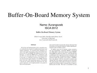
Buffer-On-Board Memory System
Buffer-On-Board Memory System. Name: Aurangozeb ISCA 2012. Outline. Introduction Modern Memory System Buffer-On-Board (BOB) Memory System BOB Simulation Suite BOB Simulation Result Limit-Case Simulation Full System Simulation Conclusion. Introduction (1/2).

Buffer-On-Board Memory System
E N D
Presentation Transcript
Buffer-On-Board Memory System Name: AurangozebISCA 2012
Outline • Introduction • Modern Memory System • Buffer-On-Board (BOB) Memory System • BOB Simulation Suite • BOB Simulation Result • Limit-Case Simulation • Full System Simulation • Conclusion
Introduction (1/2) • Modification of Memory system to cope with high speed. • Dual Inline Memory Module (DIMM) : <100 MHz speed. • Signal Integrity (i.e. Cross-talk, Reflection) issue at high speed of operation. • Reduce no. of DIMM to increase CLK speed. • Limits the total capacity • One Simple solution: • Increase capacity of single DIMM • Drawback: • Difficult to decrease DRAM capacitor size. • Cost does not scale linearly
Introduction (2/2) • FB-DIMM Memory Solution: • Advanced Memory Buffer (AMB) with DDRx DRAM to interpret packetized protocol and issue DRAM specific command. • Support fast and slow speed of operation. • Drawback: • High speed I/O of AMB: Heat & Power issue • Not cost effective • Solution from IBM / INTEL / AMD : • A single logic chip. Not for one logic chip per FB-DIMM • Control DRAM and communicate with CPU over a relatively faster and narrow bus. • New architecture using low cost DIMMs
Modern Memory System • Consideration • Ranks of memory per channel • DRAM type • No. of channels per processor
Buffer-On-Board (BOB) Memory System (1/2) • Multiple BOB Channels • Each Channel consists of LR-, R-, or U-DIMMs • Single & Simple controller for each channel • Faster and Narrower bus (Link Bus) between simple controller and CPU
Buffer-On-Board (BOB) Memory System (2/2) • Operation: • Request Packet over link bus: Address + Req. Type + Data (if write) • Translate Request into DRAM specific command (ACTIVATE, READ, WRITE etc.) and issue to DRAM Ranks. • A Command Queue: Dynamic Scheduling • Read Return Queue: Sorting after data receive • Response Packet contains: Data + Address of initial request. • BOB controller: • Address mapping • Returning data to CPU/Cache • Packetizing Request • Interpret Response packets: From & To simple controller • Encapsulation: to support narrower link bus • Use multiple clock to transmit total data. • A cross-bar switch: Any port to any link bus.
BOB Simulation Suite • Two Separate Simulators • Developed by authors and MARSSx86 • A multi-core x86 simulator developed at SUNY-Binghamton • Cycle Based Simulator written in C++ • Encapsulate: Main BOB, each BOB, Associated Link and simple controller. • Two Modes • Stand-alone: Request parameterization, Random address or trace file are issued to memory system • Full system simulation: Receive Request from MARSSx86 • Memory • A DDR3-1066 (MT41J512M4-187E) • A DDR3-1333 device (MT41J1G4-15E), and • A DDR3-1600 device (MT41J256M4-125E)
BOB Simulation Result • Two Experiments: • A limit-case simulation: random address stream is issued into a BOB memory system. • A full system simulation: an operating system is booted on an x86 processor and applications are executed • Benchmark • NAS parallel benchmarks • PARSEC benchmark suite [9] • STREAM. • Emphasized multi-threaded applications to demonstrate the types of workloads this memory architecture is likely to encounter. • Design tradeoffs: Costs such as total pin count, power dissipation, and physical space (or total DIMM count).
Limit-Case Simulation • Simple Controller & DRAM Efficiency • Optimal rank depth for each DRAM channel is between 2 and 4 • If Return Queue is full, no further read or write. • A read return queue must have at least enough capacity for four responses packets.
Limit-Case Simulation • Link Bus Configuration (1/2) • Width and speed of buses optimization: No stall the DRAM • A read-to-write request ratio of approximately 2-to-1 • Equations 1 & 2: Bandwidth required by each link bus to prevent them from negatively impacting the efficiency of each channel.
Limit-Case Simulation • Link Bus Configuration (2/2) • Weighting the response link bus more than the request : May be ideal for some application • Side-effect: Serializing the communication on unidirectional buses
Limit-Case Simulation • Multi-Channel Optimization • Multiple logically independent channels of DRAM to share the same link bus and simple controller • Reduce costs such as pin-out, logic fabrication, and physical space. • Reduce the number of simple controllers
Limit-Case Simulation • Cost Constrained Simulations • 8 DRAM channels, each with 4 ranks (32 DIMMs making 256 GB total) • CPU has up to 128 pins which can be used for data lanes • These lanes are operated at 3.2 GHz (6.4 Gb/s)
Full System Simulations • Simple Controller & DRAM Efficiency • Optimal rank depth for each DRAM channel is between 2 and 4 • If Return Queue is full, no further read or write. • A read return queue must have at least enough capacity for four responses packets.
Limit-Case Simulation • Link Bus Configuration (1/2) • Width and speed of buses optimization: No stall the DRAM • A read-to-write request ratio of approximately 2-to-1 • Equations 1 & 2: Bandwidth required by each link bus to prevent them from negatively impacting the efficiency of each channel.
Limit-Case Simulation • Link Bus Configuration (2/2) • Weighting the response link bus more than the request : May be ideal for some application • Side-effect: Serializing the communication on unidirectional buses
Limit-Case Simulation • Multi-Channel Optimization • Multiple logically independent channels of DRAM to share the same link bus and simple controller • Reduce costs such as pin-out, logic fabrication, and physical space. • Reduce the number of simple controllers
Full System Simulations • Performance & Power Trade-offs • STREAM and mcol generate the greatest average • This is due to the request mix generated during region of interest • STREAM: 46% reads and 54% writes • mcol: 99% reads.
Full System Simulations • Performance & Power Trade-offs
Full System Simulations • Address & Channel Mapping
Full System Simulations • Address & Channel Mapping
Full System Simulations • Address & Channel Mapping
Conclusion • A new memory architecture: Increase both speed and capacity. • Intermediate logic between the CPU and DIMMs. • Verified by implementing two configurations: • Limit-Case Simulation • Full System Simulation • Queue depths, proper bus configurations, and address mappings are considered to achieve peak efficiency. • Cost-constrained simulations are also performed. • The buffer-on-board architecture: An ideal near-term solution.