№ 1. Electromagnetic cannon
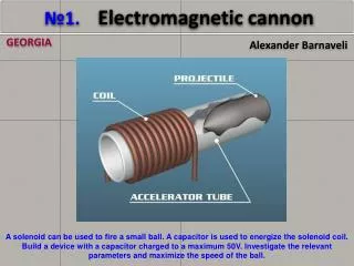
GEORGIA. Alexander Barnaveli. № 1. Electromagnetic cannon . A solenoid can be used to fire a small ball. A capacitor is used to energize the solenoid coil. Build a device with a capacitor charged to a maximum 50V . Investigate the relevant parameters and maximize the speed of the ball. .

№ 1. Electromagnetic cannon
E N D
Presentation Transcript
GEORGIA Alexander Barnaveli №1. Electromagnetic cannon A solenoid can be used to fire a small ball. A capacitor is used to energize the solenoid coil. Build a device with a capacitor charged to a maximum 50V. Investigate the relevant parameters and maximize the speed of the ball.
Presentation Plan • Principles of the Electro-Magnetic Cannon action, • Experiment (EM cannon in action); • Preliminary theoretical consideration; • Our version of Coil-Gun construction; • Results. Progress achieved by our optimization.
Principles of EM Cannon Action Components: • Solenoid (coil) • Tube (barrel) • Ferromagnetic projectile • Power Source / Capacitors Electric current in the solenoid creates the magnetic field External magnetic field causes alignment of micro-current domains in ferromagnetic projectile The Projectile gets magnetized The pole signs of the coil and of projectile are mutually symmetric 4. The projectile is attracted to the coil center Figures 1,2,3
"EM Cannon middle-point" Problem • After passing the coil center the projectile will be attracted backwards. • In the coil center the electric current must be turned off; • We must use the special switching scheme.
Entrance Exit
Preliminary Theoretical Considerations F1=B1P1 F2=B2P2 The force applied to the projectile by solenoid: [http://www.coilgun.eclipse.co.uk/coilgun_fundamentals_1.html] (1) N – number of turns (loops) in solenoid, I- current, - the Magnetic Flux Gradient at the projectile with respect to displacement in tube ( ) Fig 4 The sum of the forces applied to the dipole by field gradient Fig 5. Change of the field linked to the projectile Construction of coil-gun must provide themaximalvalue of the expression N·I·
Preliminary Theoretical Considerations a) Optimal Barrel b) Optimal Projectile c) Optimal dimensions of Solenoid d) Optimal number of Turns / Wire Diameter e) Capacitors
f) Iron Shell Pro: The iron shell increases the concentration of the magnetic field power lines at the ends of the coil. Shell supports Φ and Con: • Shellincreasesthe inductance of the coil: L~μ(µ- magnetic permeability of the shell) Larger strength of induced voltage (ElectroMotive Force – EMF)decreasing the current change rate • Parasite currents. Iron shell Solenoid Magnetic lines in case of iron shell
g) Switching off the coil power supply • After passing of the coil center the acting force changes its sign (direction) • The projectile starts to slow down • For the maximal speed we have to switch offthe power supply when the projectile reaches the centre. The force, applied to projectile
Our construction of coil gun We focused our attention on: • Optimization of the solenoid shell: Only closing washers - solenoids (B, C) (2 From side of projectile load and 1 from back side) 2 mm thick iron. - Higher gradient dΦ/dxat the place of projectile input - No significant increasing of coil inductance L - No significant parasite current - No suppression of discharge current. • Optimization of the solenoid center problem solution: - Switching off the circuit when the projectile reaches solenoid center (A,B). - Enhanced “Consequent switching-off” scheme - solenoid (C). (A) (B) (C)
Circuit Scheme No1 Switching - off at the middle-point
Impulse Not cut Cut
Enhanced scheme Consequent switching-off the parts of solenoid behind the projectile About 17% higher velocity Additional EMF in front parts !! 42 m/sec With 300Vandenhanced scheme we get
Parameters of our coil gun We experimented with two basic configurations (50V and 300V): (A) (B) (C)
Batteries of capacitors Our coils Full shell 300V (A) 900 µF Optimal shell (B) 50V 12000 µF Consequent Switching off (C)
Projectiles • We have chosen following projectiles: • 6 mm * 30 mm • 6 mm * 15 mm, soft iron • 6 mm * 10 mm • 6 mm=D Ball, of soft iron
Shots Shot
Velocity 50v optimal shield 26.3 m/s 27.5 m/s 26.7 m/s 15 mm projectile 6 mm Ball 10 mm Projectile 300v +20% +17%
Voltage 300 V • Capacity - 900 µF battery of capacitors (20 x 45 µF). • Projectile 6mm x 15mm 40% increase of result Projectile Velocity (m/sec) 50 45 40 35 30 25 20 42m/sec 36m/sec 30m/sec Consequent Switching off Optimal shell Full shell Model №
Efficiency Capacitor energy difference Projectile kinetic Energy Efficiency For Uinitial=300v ; Ufinal=260v ; m = 3.4g ; C=900µF ; v= 36 m/sec χ~21% For consequent switching scheme Uinitial=300V ; Ufinal=245V ; v= 42 m/sec χ~22%
Low-current switching-off scheme • Switching-off the scheme by switching-off the circuit of the thyratrongreed. • Much lower current goes through the sliding contacts. • Lower energy-loss.
Conclusion • Found out that effectiveness of EM cannon strongly depends on: • Optimal external Iron shell • Optimal scheme of Switching off the solenoid power • We show that Iron shell must consistonly of closing washers : Velocity --> +~20% • We proposed advanced solution with “consequent switching-off” scheme : Velocity --> extra+~17% • Both optimizations together gave 40%increase of velocity • We obtained ~42 m/secvelocity. Action
Thank you for attention! • References • http://www.coilgun.eclipse.co.uk/coilgun_fundamentals_1.html . • http://www.coilgun.info/theory/externaliron.htm
a) Optimal Barrel • It must be made of dielectric; • Accelerator barrel must have walls as thin as possible • Its diameter must fit the diameters of the coil and projectile. Fig.6 b) Optimal Projectile • Projectile must be made of ferromagneticor of magnet; • We consider the projectiles made of soft ferromagnetic (i.e. easily magnetized and de-magnetized); • So we use the projectiles, made ofsoft iron; • To soften the iron we baked it out in the gas flame; • Projectile diameter must fit the solenoid inner diameter; • We tried the projectiles of different length - 6mm - 30mm
c) Optimal dimensions of Solenoid • Thelengthof solenoid - several lengths of the projectile. No sense of the long solenoid: near the centerdΦ/dx ≈ 0 • Theinner diameter must be close (just a little exceeding) to projectile diameter (thin walls of tube) • The outer diameter must not be large, because the field inside the loop so the contribution of large (outer) Loops is small.
d) Optimal number of Turns / Wire Diameter Optimal number of Loops (Turns) • Pro: more turns N - larger F • Con: more turns N - larger resistance R and inductance L: • µ0- magnetic constant, • µi- magnetic permeability of the coil core, • S- area of the coil turn , • N- the number of turns, lsol- the length of the coil. • (2) where - • Larger strength of induced voltage (ElectroMotive Force - EMF.) • (3) • Slower growth of I when the circuit switch on. Optimal Wire Diameter • Pro: Larger wire diameter - smaller Rand larger I • Con: Larger wire diameter - less turns (smaller N) • So it is necessary to optimize I·N
e) Capacitors • The power source of Gauss Gun is the battery of capacitors • The energy, accumulated in capacitors (4) We must choose capacitors of the maximalC. Also, the higher voltage - the better result 300V 50V 900 µF 12 000 µF
RailGun A rail gun works with magnetic fields. Unlike the coil gun and Gauss cannons, rail guns use rails to generate a magnetic pull/push rather than coils of wire. As shown the rail gun runs electricity through one of the rails which then crosses through the bullet itself and goes back through the other rail causing a magnetic field that pushes the projectile forward.