Download
1 / 112
1.13k likes | 1.42k Views
MOBILE COMMUNICATION. UNIT – III WIRELESS LAN. Table of Contents. 7. Wireless LAN 7.1. Infra red vs radio transmission 7.2. Infrastructure and ad-hoc network 7.3. IEEE 802.11 7.3.1. System architecture 7.3.2. Protocol architecture

E N D
MOBILE COMMUNICATION UNIT – III WIRELESS LAN
Table of Contents 7. Wireless LAN 7.1. Infra red vs radio transmission 7.2. Infrastructure and ad-hoc network 7.3. IEEE 802.11 7.3.1. System architecture 7.3.2. Protocol architecture 7.3.3. Physical layer 7.3.4. Medium access control layer 7.3.5. MAC management 7.3.6. 802.11b 7.3.7. 802.11a 7.3.8. Newer developments
Table of Contents 7.4. HIPERLAN 7.4.1. Historical: HIPERLAN1 7.4.2. WATM 7.4.3. BRAN 7.4.4. HiperLAN2 7.5. Bluetooth 7.5.1. User scenarios 7.5.2. Architecture 7.5.3. Radio layer 7.5.4. Baseband layer 7.5.5. Link manager protocol
Table of Contents 7.5.6. L2CAP 7.5.7. Security 7.5.8. SDP 7.5.9. Profiles 7.5.10. IEEE 802.15
7. Wireless LAN • The global goal of WLANs is to replace office cabling, to enable tether less access to the internet and, to introduce a higher flexibility for ad-hoc communication in, e.g., group meetings. • Some advantages of WLANs are: • Flexibility: Within radio coverage, nodes can communicate without further restriction. • Planning • Design • Robustness: Wireless networks can survive disasters • Cost • WLANs also have several disadvantages: • Quality of service • Proprietary solutions • Restrictions • Safety and security
7. Wireless LAN • Many different, and sometimes competing, design goals have to be taken into account for WLANs to ensure their commercial success: • Global operation • Low power • License-free operation • Robust transmission technology • Simplified spontaneous cooperation • Easy to use • Protection of investment • Safety and security • Transparency for applications
7.1 Infra red vs radio transmission • Two different basic transmission technologies can be used to set up WLANs. • One technology is based on the transmission of infra red light (e.g., at 900 nm wavelength), the other one, which is much more popular, uses radio transmission in the GHz range (e.g., 2.4 GHz in the license-free ISM band). • Infra red technology uses diffuse light reflected at walls, furniture etc. or directed light if a line-of-sight (LOS) exists between sender and receiver. • Senders can be simple light emitting diodes (LEDs) or laser diodes. • Photodiodes act as receivers.
7.2 Infrastructure and ad-hoc networks • Infrastructure networks not only provide access to other networks, but also include forwarding functions, medium access control etc. • In these infrastructure-based wireless networks, communication typically takes place only between the wireless nodes and the access point, but not directly between the wireless nodes. • The access point does not just control medium access, but also acts as a bridgeto other wireless or wired networks. • The design of infrastructure-based wireless networks is simpler because most of the network functionality lies within the access point, whereas the wireless clients can remain quite simple. • This type of network can use different access schemes with or without collision.
7.2 Infrastructure and ad-hoc networks • If only the access point controls medium access, nocollisions are possible. • This setting may be useful for quality of service guarantees such as minimum bandwidth for certain nodes. • Infrastructure-based networks lose some of the flexibility wireless networks can offer, e.g., they cannot be used for disaster relief in cases where no infrastructure is left. • Typical cellular phone networks are infrastructure-based networks for a wide area. • Also satellite-based cellular phones have an infrastructure – the satellites. • Infrastructure does not necessarily imply a wired fixed network.
7.2 Infrastructure and ad-hoc networks • Ad-hoc wireless networks, however, do not need any infrastructure to work. • Each node can communicate directly with other nodes, so no access point controlling medium access is necessary. • Nodes within an ad-hoc network can only communicate if they can reach each other physically, i.e., if they are within each other’s radio range or if other nodes can forward the message. • In ad-hoc networks, the complexity of each node is higher because every node has to implement medium access mechanisms, mechanisms to handle hidden or exposed terminal problems, and perhaps priority mechanisms, to provide a certain quality of service.
7.2 Infrastructure and ad-hoc networks • This type of wireless network exhibits the greatest possible flexibility as it is, for example, needed for unexpected meetings, quick replacements of infrastructure or communication scenarios far away from any infrastructure. • Ad-hoc networks might only have selected nodes with the capabilities of forwarding data. • Most of the nodes have to connect to such a special node first to transmit data if the receiver is out of their range.
7.3 IEEE 802.11 • The IEEE standard 802.11 (IEEE, 1999) specifies the most famous family of WLANs in which many products are available. • As the standard’s number indicates, this standard belongs to the group of 802.x LAN standards, e.g., 802.3 Ethernet or 802.5 Token Ring. • This means that the standard specifies the physicaland medium access layer adapted to the special requirements of wireless LANs, but offers the same interface as the others to higher layers to maintain interoperability. • The primary goal of the standard was the specification of a simple and robust WLAN which offers time-bounded and asynchronous services.
7.3 IEEE 802.11 • The MAC layer should be able to operate with multiple physical layers, each of which exhibits a different medium sense and transmission characteristic. • Candidates for physical layers were infrared and spread spectrum radio transmission techniques. • Additional features of the WLAN should include the support of power management to save battery power, the handling of hidden nodes, and the ability to operate worldwide. • The 2.4 GHz ISM band, which is available in most countries around the world, was chosen for the original standard. • Data rates envisaged for the standard were 1 Mbit/s mandatory and 2 Mbit/s optional.
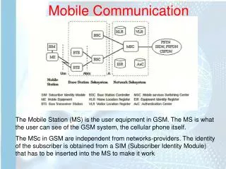
7.3 IEEE 802.11 7.3.1 System architecture • Wireless networks can exhibit two different basic system architectures: infrastructure-based or ad-hoc. • In infrastructure network Several nodes, called stations (STAi), are connected to access points (AP). • Stations are terminals with access mechanisms to the wireless medium and radio contact to the AP. • The stations and the AP which are within the same radio coverage form a basic service set (BSSi). • A distribution system connects several BSSs via the AP to form a single network and thereby extends the wireless coverage area. • This network is now called an extended service set (ESS) and has its own identifier, the ESSID.
7.3 IEEE 802.11 • Figure shows the components of an infrastructure and a wireless part as specified for IEEE 802.11.
7.3 IEEE 802.11 • Without knowing the ESSID it should not be possible to participate in the WLAN. • The distribution system connects the wireless networks via the APs with a portal, which forms the interworking unit to other LANs. • Stations can select an AP and associate with it. • The APs support roaming, the distribution system handles data transfer between the different APs. • APs provide • synchronization within a BSS, • support power management, and • can control medium access to support time-bounded service.
7.3 IEEE 802.11 • IEEE 802.11 allows the building of ad-hoc networks between stations, thus forming one or more independent BSSs (IBSS). • In this case, an IBSS comprises a group of stations using the same radio frequency. • Stations STA1, STA2, and STA3 are in IBSS1, STA4 and STA5 in IBSS2. • This means for example that STA3can communicate directly with STA2 but not with STA5.
7.3 IEEE 802.11 7.3.2 Protocol architecture • Figure shows the most common scenario: an IEEE 802.11 wireless LAN connected to a switched IEEE 802.3 Ethernet via a bridge.
7.3 IEEE 802.11 • The IEEE 802.11 standard only covers the physical layer PHY and medium access layer MAC like the other 802.x LANs do. • The physical layer is subdivided into the physical layer convergence protocol (PLCP) and the physical medium dependent sub layer PMD.
7.3 IEEE 802.11 • The basic tasks of the MAC layer comprise medium access, fragmentation of user data, and encryption. • The PLCP sub layer provides a carrier sense signal, called clear channel assessment (CCA), and provides a common PHY service access point (SAP) independent of the transmission technology. • Finally, the PMDsub layer handles modulation and encoding/decoding of signals. • Apart from the protocol sub layers, the standard specifies management layers and the station management. • The MAC management supports the association and re-association of a station to an access point and roamingbetween different access points.
7.3 IEEE 802.11 • It also controls authentication mechanisms, encryption, synchronization of a station with regard to an access point, and power management to save battery power. • MACmanagement also maintains the MACmanagement information base (MIB). • The main tasks of the PHY management include channel tuning and PHY MIB maintenance. • Finally, station management interacts with both management layers and is responsible for additional higher layer functions.
7.3 IEEE 802.11 7.3.3 Physical layer • IEEE 802.11 supports three different physical layers: • one layer based on infra red and • two layers based on radio transmission (primarily in the ISM band at 2.4 GHz, which is available worldwide). • All PHY variants include the provision of the clear channel assessmentsignal (CCA). • This is needed for the MAC mechanisms controlling medium access and indicates if the medium is currently idle. • The PHY layer offers a service access point (SAP) with 1 or 2 Mbit/s transfer rate to the MAC layer.
7.3 IEEE 802.11 7.3.3.1 Frequency hopping spread spectrum • Frequency hopping spread spectrum (FHSS) is a spread spectrum technique which allows for the coexistenceof multiple networks in the same area by separating different networks using differenthopping sequences. • The original standard defines 79 hopping channels for North America and Europe, and 23 hopping channels for Japan. • The selection of a particular channel is achieved by using a pseudo-random hopping pattern. • National restrictions also determine further parameters, e.g., maximum transmit power is • 1 W in the US, • 100 mWEIRP (equivalent isotropic radiated power) in Europe and • 10 mW/MHz in Japan.
7.3 IEEE 802.11 • The standard specifies Gaussian shaped FSK (GFSK), as modulation for the FHSS PHY. • For 1 Mbit/s a 2 level GFSK is used, a 4 level GFSK for 2 Mbit/s. • While sending and receiving at 1 Mbit/s is mandatory for all devices, operation at 2 Mbit/s is optional. • Figure 7.7 shows a frame of the physical layer used with FHSS. • The frame consists of two basic parts, the PLCPpart and the payload part. • While the PLCP part is always transmitted at 1 Mbit/s, payload, i.e. MAC data, can use 1 or 2 Mbit/s.
7.3 IEEE 802.11 • Synchronization: • The PLCP preamble starts with 80 bit synchronization, which is a 010101... bit pattern. • This pattern is used for synchronization of potential receivers and signal detection by the CCA. • Start frame delimiter (SFD): • The following 16 bits indicate the start of the frame and provide frame synchronization. • The SFD pattern is 0000110010111101. • PLCP_PDU length word (PLW): • This first field of the PLCP header indicates the length of the payload in bytes including the 32 bit CRC at the end of the payload. PLW can range between 0 and 4,095.
7.3 IEEE 802.11 • PLCP signaling field (PSF): • This 4 bit field indicates the data rate of the payload following. • All bits set to zero (0000) indicates the lowest data rate of 1 Mbit/s. • The granularity is 500 kbit/s, thus 2 Mbit/s is indicated by 0010 and the maximum is 8.5 Mbit/s (1111). • This system obviously does not accommodate today’s higher data rates. • Header error check (HEC): • Finally, the PLCP header is protected by a 16 bit checksum with the standard ITU-T generator polynomial G(x) = x16+ x12+ x5+ 1.
7.3 IEEE 802.11 7.3.3.2 Direct sequence spread spectrum • Direct sequence spread spectrum (DSSS) is the alternative spread spectrum method separating by code and not by frequency. • In the case of IEEE 802.11 DSSS, spreading is achieved using the 11-chip Barker sequence (+1, –1, +1, +1, –1, +1, +1, +1, –1, –1, –1). • The key characteristics of this method are its robustness against interference and its insensitivity to multipath propagation. • IEEE 802.11 DSSS PHY also uses the 2.4 GHz ISM band and offers both 1 and 2 Mbit/s data rates. • The system uses differential binary phase shift keying (DBPSK) for 1 Mbit/s transmission and differential quadrature phase shift keying (DQPSK) for 2 Mbit/s as modulation schemes.
7.3 IEEE 802.11 • The maximum transmit power is 1 W in the US, 100 mW EIRP in Europe and 10 mW/MHz in Japan. • The symbol rate is 1 MHz, resulting in a chipping rate of 11 MHz. • All bits transmitted by the DSSS PHY are scrambled with the polynomial s(z) = z7+ z4+ 1 for DC blocking and whitening of the spectrum. • Figure shows a frame of the physical layer using DSSS. • The frame consists of two basic parts, the PLCP part and the payload part.
7.3 IEEE 802.11 • Synchronization : • The first 128 bits are not only used for synchronization, but also gain setting, energy detection (for the CCA), and frequency offset compensation. • The synchronization field only consists of scrambled 1 bits. • Start frame delimiter (SFD) : • This 16 bit field is used for synchronization at the beginning of a frame and consists of the pattern 1111001110100000. • Signal : • Originally, only two values have been defined for this field to indicate the data rate of the payload. • The value 0x0A indicates 1 Mbit/s (and thus DBPSK), 0x14 indicates 2 Mbit/s (and thus DQPSK).
7.3 IEEE 802.11 • Service : • This field is reserved for future use; however, 0x00 indicates an IEEE 802.11 compliant frame. • Length : • 16 bits are used in this case for length indication of the payload in microseconds. • Header error check (HEC) : • Signal, service, and length fields are protected by this checksum using the ITU-T CRC-16 standard polynomial.
7.3 IEEE 802.11 7.3.3.3 Infra red • The PHY layer, which is based on infra red (IR) transmission, uses near visible light at 850–950 nm. • Infra red light is not regulated apart from safety restrictions (using lasers instead of LEDs). • The standard does not require a line-of-sight between sender and receiver, but should also work with diffuse light. • This allows for point-to-multipoint communication. • The maximum range is about 10 mif no sunlight or heat sources interfere with the transmission. • Typically, such a network will only work in buildings, e.g., classrooms, meeting rooms etc.
7.3 IEEE 802.11 7.3.4 Medium access control layer • The MAC layer has to control medium access, but it can also offer support for roaming, authentication, and power conservation. • The basic services provided by the MAC layer are the mandatoryasynchronous data service and an optional time-bounded service. • While 802.11 only offers the asynchronous service in ad-hoc network mode, both service types can be offered using an infrastructure-based network together with the access point coordinating medium access. • The asynchronous service supports broadcast and multi-cast packets, and packet exchange is based on a ‘best effort’ model, i.e., no delay bounds can be given for transmission.
7.3 IEEE 802.11 • The following three basic access mechanisms have been defined for IEEE 802.11: • The mandatory basic method based on a version of CSMA/CA, • An optionalmethod avoiding the hidden terminal problem, and • A contention-free polling method for time-bounded service. • The first two methodsare also summarized as distributed coordination function (DCF), the third method is called point coordination function (PCF). • DCFonly offers asynchronous service, while PCF offers both asynchronous and time-bounded servicebut needs an access point to control medium access and to avoid contention. • The MAC mechanisms are also called distributed foundation wireless medium access control (DFWMAC).
7.3 IEEE 802.11 • Figure shows the three different parameters that define the priorities of medium access. • The values of the parameters depend on the PHY and are defined in relation to a slot time. • Slot time is derived from the medium propagation delay, transmitter delay, and other PHY dependent parameters. • Slot time is 50 µs for FHSS and 20 µs for DSSS.
7.3 IEEE 802.11 • The medium, as shown, can be busy or idle (which is detected by the CCA). • If the medium is busy this can be due to data frames or other control frames. • During a contention phase several nodes try to access the medium. • Short inter-frame spacing (SIFS): • The shortest waiting time for medium access (so the highest priority) is defined for short control messages, such as acknowledgements of data packets or polling responses. • For DSSS SIFS is 10 µs and for FHSS it is 28 µs.
7.3 IEEE 802.11 • PCF inter-frame spacing (PIFS): • A waiting time between DIFS and SIFS (and thus a medium priority) is used for a time-bounded service. • An access point polling other nodes only has to wait PIFS for medium access. • PIFS is defined as SIFS plus one slot time. • DCF inter-frame spacing (DIFS): • This parameter denotes the longest waiting time and has the lowest priority for medium access. • This waiting time is used for asynchronous data service within a contention period. • DIFS is defined as SIFS plus two slot times.
7.3 IEEE 802.11 7.3.4.1 Basic DFWMAC-DCF using CSMA/CA • The mandatory access mechanism of IEEE 802.11 is based on carrier sense multiple access with collision avoidance(CSMA/CA), which is a random access scheme with carrier sense and collision avoidance through random backoff. • The basic CSMA/CA mechanism is shown in Figure.
7.3 IEEE 802.11 • If the medium is idle for at least the duration of DIFS, a node can access the medium at once. • This allows for short access delay under light load. • But as more and more nodes try to access the medium, additional mechanisms are needed. • If the medium is busy, nodes have to wait for the duration of DIFS, entering a contention phase afterwards. • Each node now chooses a random backoff time within a contention window and delays medium access for this random amount of time. • The node continues to sense the medium. • As soon as a node senses the channel is busy, it has lost this cycle and has to wait for the next chance, i.e., until the medium is idle again for at least DIFS.
7.3 IEEE 802.11 • But if the randomized additional waiting time for a node is over and the medium is still idle, the node can access the medium immediately. • Obviously, the basic CSMA/CA mechanism is not fair. • Independent of the overall time a node has already waited for transmission; each node has the same chances for transmitting data in the next cycle. • To provide fairness, IEEE 802.11 adds a backoff timer. • Again, each node selects a random waiting time within the range of the contention window. • If a certain station does not get access to the medium in the first cycle, it stops its backoff timer, waits for the channel to be idle again for DIFS and starts the counter again.
7.3 IEEE 802.11 • As soon as the counter expires, the node accesses the medium. • This means that deferred stations do not choose a randomized backoff time again, but continue to count down. • Stations that have waited longer have the advantage over stations that have just entered, in that they only have to wait for the remainder of their backoff timer from the previous cycle(s). • A collision triggers a retransmission with a new random selection of the backoff time. • Retransmissions are not privileged. • Still, the access scheme has problems under heavy or light load. • Depending on the size of the contention window (CW), the random values can either be too close together (causing too many collisions) or the values are too high (causing unnecessary delay).
7.3 IEEE 802.11 • Figure shows a sender accessing the medium and sending its data. • But now, the receiver answers directly with an acknowledgement (ACK). • The receiver accesses the medium after waiting for a duration of SIFS so no other station can access the medium in the meantime and cause a collision.
7.3 IEEE 802.11 • The other stations have to wait for DIFS plus their backoff time. • This acknowledgement ensures the correct reception (correct checksum CRC at the receiver) of a frame on the MAC layer, which is especially important in error-prone environments such as wireless connections. • If no ACK is returned, the sender automatically retransmits the frame. • But now the sender has to wait again and compete for the access right. • There are no special rules for retransmissions. • The number of retransmissions is limited, and final failure is reported to the higher layer.
7.3 IEEE 802.11 7.3.4.2 DFWMAC-DCF with RTS/CTS extension • Figure illustrates the use of RTS and CTS. • After waiting for DIFS (plus a random backoff time if the medium was busy), the sender can issue a request to send (RTS) control packet. • The RTS packet thus is not given any higher priority compared to other data packets.
7.3 IEEE 802.11 • The RTS packet includes the receiver of the data transmission to come and the duration of the whole data transmission. • This duration specifies the time interval necessary to transmit the whole data frame and the acknowledgement related to it. • Every node receiving this RTS now has to set its net allocation vector (NAV) in accordance with the duration field. • The NAV then specifies the earliest point at which the station can try to access the medium again. • If the receiver of the data transmission receives the RTS, it answers with a clear to send (CTS) message after waiting for SIFS. • This CTS packet contains the duration field again and all stations receiving this packet from the receiver of the intended data transmission have to adjust their NAV. • This mechanism reserves the medium for one sender exclusively.
7.3 IEEE 802.11 • However, the mechanism of fragmenting a user data packet into several smaller parts should be transparent for a user. • The MAC layer should have the possibility of adjusting the transmission frame size to the current error rate on the medium. • The IEEE 802.11 standard specifies a fragmentation mode. • Again, a sender can send an RTS control packet to reserve the medium after a waiting time of DIFS. • This RTS packet now includes the duration for the transmission of the first fragment and the corresponding acknowledgement. • A certain set of nodes may receive this RTS and set their NAV according to the duration field. • The receiver answers with a CTS, again including the duration of the transmission up to the acknowledgement. • A set of receivers gets this CTS message and sets the NAV.
7.3 IEEE 802.11 • The new aspect of this fragmentation mode is that it includes another duration value in the frame frag1. • This duration field reserves the medium for the duration of the transmission following, comprising the second fragment and its acknowledgement.
7.3 IEEE 802.11 7.3.4.3 DFWMAC-PCF with polling • The two access mechanisms presented so far cannot guarantee a maximum access delay or minimum transmission bandwidth. • To provide a time-bounded service, the standard specifies a point coordination function (PCF) on top of the standard DCF mechanisms. • Using PCF requires an access point that controls medium access and polls the single nodes. • The point coordinator in the access point splits the accesstime into super frame periods as shown in Figure. • A super frame comprises a contention free period and a contention period. • The contention period can be used for the two access mechanisms presented above.