SHALLOW FOUNDATIONS
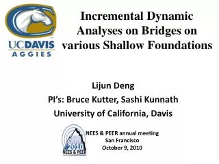
SHALLOW FOUNDATIONS. By – C.M.GUPTA Sr.Prof /Br.2 IRICEN. Design of Formation/Foundation. Location Stress Settlement . Types of foundations. Shallow Foundation ( Df < B) Footing Raft/Mat Isolated Continuous Rectangular Strip

SHALLOW FOUNDATIONS
E N D
Presentation Transcript
SHALLOW FOUNDATIONS By – C.M.GUPTASr.Prof/Br.2 IRICEN
Design of Formation/Foundation • Location • Stress • Settlement
Types of foundations Shallow Foundation (Df< B) Footing Raft/Mat Isolated Continuous Rectangular Strip Square Strap Circular Combined Deep Foundation (Df > B) Deep footings Piles Well/Cassions
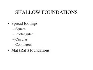
ShallowFoundations • Common Types of Footing • Strip footing • Spread Footing
Common Types of Footing • Combined Footing • Raft or Mat footing
Shallow foundations • IS 1904:1986 is code of practice for design and construction of foundations in soils: General requirements • As per IS 1904:1986. shallow foundations are such types of foundations in which load transference is primarily through shear resistance of the bearing strata ( the fractional resistance of soil above bearing strata is not taken into consideration ) and are laid normally upto a depth of 3 m. • As per IS 6403:1981 (Determination of bearing capacity of shallow foundations), shallow foundations are those whose width is greater than depth.
Factors affecting choice of foundation • Function of the Structure – Residential, Commercial, Bridges etc. • Loads coming from the structure • Subsoil conditions • Relative cost of foundation in relation to superstructure
Factors affecting Depth of Shallow Foundations • Depth of top soil or filled-up soil • Depth of poor surface deposit such as peat, muck, sanitary land fill • Location of ground water table and its seasonal variation • Depth of poor or better underlying strata • Depth of adjacent footing
Location and depth of Foundation • IS:1904-1986: Minimum depth of foundation = 0.50 m. • Foundation shall be placed below the zone of • Excessive volume change due to moisture variation (usually exists within 1.5 to 3.5 m depth) • Topsoil or organic material • Foundations adjacent to flowing water (flood water, rivers, etc.) shall be protected against scouring. • A raised water table may cause damage to the foundation by • Floating the structure • Reducing the effective stress beneath the foundation • Water logging around the building: proper drainage system around the foundation may be required so that water does not accumulate.
Location and depth of Foundation • Footings on surface rock or sloping rock faces • Shallow rock beds: foundation on the rock surface after chipping • Rock bed with slope: 1010provide dowel bars of minimum 16 mm diameter and 225 mm embedment into the rock at 1 m spacing. • Footings adjacent to existing structures • Minimum horizontal distance between the foundations shall not be less than the width of larger footing. Otherwise, the principal of 2H:1V distribution be used to minimize influence to old structure • Proper care is needed during excavation phase of foundation construction beyond merely depending on the 2H:1V criteria. Excavation may cause settlement to old foundation due to lateral bulging in the excavation and/or shear failure due to reduction in overburden stress in the surrounding of old foundation
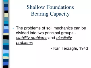
Provisions of IS: 1080:1985 IS:1080:1985 is code of practice for design and construction of shallow foundations in soils 3. GENERAL 3.1 The shallow foundations cover such type of foundation in which the load transference is primarily through shear resistance of the bearing strata ( the frictional resistance of soil above bearing strata is not taken into consideration ) and are laid normally up to depth of 3 m.
3. GENERAL Provisions of IS: 1080:1985 • 3.1.1 These foundations are of following types • a) Pad or Spread - In such type of foundation, which is constructed of masonry and/or concrete ( plain or reinforced ) and is isolated, the loads of a structure is transferred to the ground in such a manner that the safe bearing pressure is not exceeded. • b) Strip-- Such type of foundation provides continuous and longitudinal bearing for loads carried by vertical elements, such as continuous wall foundation beams or the like.
4. DESIGN CONSIDERATION Provisions of IS: 1080:1985 4.1 In such type of foundations wherever the resultant of the load deviates from the centre line by more than 1/6 of its least dimension at the base of footing, it should be suitably reinforced. 4.2 For continuous wall foundations (plain or reinforced ) adequate reinforcement should be provided particularly at places where there is abrupt change in magnitude of load or variation in ground support.
4. DESIGN CONSIDERATION Provisions of IS: 1080:1985 4.3 On sloping sites the foundation should have a horizontal bearing and stepped and lapped at changes of levels for a distance at least equal to the thickness of foundation or twice the height of step whichever is greater. The steps should not be of greater height than thickness of the foundations.
4. DESIGN CONSIDERATION Provisions of IS: 1080:1985 4.4 Ground Beams The foundation can also have the ground beam for transmitting the load. The ground beam carrying a load bearing wall should be designed to act with the wall forming a composite beam, when both are of reinforced concrete and structurally connected by reinforcement. The ground beam of reinforced concrete structurally connected to reinforced brick work can also be used.
4. DESIGN CONSIDERATION Provisions of IS: 1080:1985 4.5 Dimensions of Foundation 4.5.1 The dimensions of the foundation in plan should be such as to support loads as given in IS: 1904-1985. The width of the footings shall be such that maximum stress in the concrete or masonry is within the permissible limits. The width of wall foundation shall not be less than that given by: B= W + 30 cm where B = width at base in cm, and W = width of supported wall in cm.
4. DESIGN CONSIDERATION Provisions of IS: 1080:1985 4.6 In the base of foundations for masonry foundation it is preferable to have the steps in multiples of thickness of masonry unit. 4.7 The plan dimensions of excavation for foundations should be wide enough to ensure safe and efficient working.
4. DESIGN CONSIDERATION Provisions of IS: 1080:1985 4.8 Unreinforced foundation may be of concrete or masonry ( stone or brick ) provided that angular spread of load from the pier or bed plate to the outer edge of the ground bearing is not more than 1 V to 1/2 H to masonry or 1 V to 1 H for cement concrete and 1 V to 2/3H for lime concrete. The minimum thickness of the foundation of the edge should not be less than 150 mm. In case the depth to transfer the load to the ground bearing is less than the permissible angle of spread, the foundations should be reinforced.
Provisions of IS: 1080:1985 4. DESIGN CONSIDERATION 4.9 If the bottom of a pier is to be belled so as to increase its load carrying capacity such bell should be at least 30 cm thick at its edge. The sides should be sloped at an angle of not less than 450 with the horizontal. The least dimension should be 60 cm (circular, square or rectangular). The design should allow for the vertical tilt of the pier by 1 percent of its height.
4. DESlGN CONSIDERATION Provisions of IS: 1080:1985 4.10 If the allowable bearing capacity is available only at a greater depth, the foundation can be rested at a higher level for economic considerations and the difference in level between the base of foundation and the depth at which the allowable bearing capacity occurs can be filled up with either: (a) concrete of allowable compressive strength not less than the allowable bearing pressure, or
4. DESIGN CONSIDERATION Provisions of IS: 1080:1985 (b) in compressible fill material, for example, sand, gravel, etc, in which case the width of the fill should be more than the width of the foundation by an extent of dispersion of load from the base of the foundation on either side at the rate of 2 vertical to 1 horizontal. 4.11 The cement concrete foundation (plain or reinforced ) should be designed in accordance with IS : 456-1978 and masonry foundation in accordance with IS : 1905-1980.
5. CONSTRUCTION Provisions of IS: 1080:1985 5.1 The cement concreting ( plain and reinforced ) in the foundation should be done in accordance with the provision given in IS : 456-1978. 5.2 The stone masonry construction should conform to IS : 1597 ( Parts 1 and 2 )-1967: and brick masonry construction should conform to IS : 2212-1962.
5. CONSTRUCTION Provisions of IS: 1080:1985 5.3 The lime concrete should be done in accordance with the provisions given in IS : 2541-1977 or IS : 5817-1970. 5.4 Masonry should be constructed over the base concrete after curing the base of concrete for at least 3 days. Before laying concrete, the bed of the foundation pit/trench should be thoroughly compacted by manual Ramming.
Provisions of Bridge Sub structure and Foundation code General Design Criteria • Preferably locate on a firm ground having stable strata. • Should fulfill following basic requirements • Safety against strength failure. • Safety against deformation and differential settlement. • Allowable bearing pressure shall be taken lessor of • Net ultimate bearing capacity / 2.5 • maximum allowable pressure on foundation without causing excessive settlement(>25mm or excessive differential settlement) • In open foundations, resultant lie within middle third • Depth of foundation in soil > 1.75m below scour level. • Shall not normally rest on compressible soils.
Sub- soil Investigations • Scope • To determine nature, extent and engineering properties of soil/ rock strata and ground water table. • Use IS:1892, 6935, 2720,1498, IRC:78 for guidance • Subsurface investigation be carried out during three stages • Reconnaissance Survey • Bad locations for foundations are avoided • Reliable data from geological and topographical maps scrutinized • Preliminary Survey • Scope restricted to determine depth, extent, composition, characteristics of various strata • Final Location Survey • Detail tests to design safe and economical structure.
Information to be obtained during sub-surface investigation • Site Plan • Cross Sections along the proposed bridge • Load conditions shown on a schematic plan, indicating design combination of loads transmitted to the foundation • Environmental factor • Geo-technical Information • Modulus of elasticity and Modulus of sub-grade reaction • A review of performance of a similar structure • Assess possible effects on existing structure
METHODS OPEN FOUNDATIONS • TRIAL PIT METHOD- • SOIL CLASSIFICATION BY VISUAL INSPECTION OR BY, • SIMPLE CLASSIFICATION TESTS • SAFE BEARING CAPACITY MAY BE ASSUMED AS PER TABLE DEEP FOUNDATIONS • BORE HOLES –SAMPLES AT EVERY 1.5m • INSITU FIELD TESTS – FOR COHESIONLESS SOILS
SHALLOW / OPEN FOUNDATIONS • NOT RESTING ON COMPRESSIBLE SOIL • DEPTH OF FOUNDATION IN • SOIL – 1.75 m BELOW ANTICIPATED SCOUR LINE • KEY IN • HARD ROCK – 0.30 m • SOFT ROCK – 1.5 m • RESULTANT OF ALL THE FORCES AT THE BASE- • WITHIN ⅓rd FOR – FOR SOILS • WITHIN ½ FOR - ROCK
Foundation in Non-cohesive strata • BEARING CAPACITY by • 1. Plate Load Test • IS 1888:1982 • 2, Standard Penetration Test (SPT) • IS 2131:1981 • 3. Static Cone Test (CPT) • IS 4968 Part 3:1976/1987 • Guidance of IS 6403, 2911 (Pt.I&IV), 2131, 4968 (Pt I&III), 1888 & 1904 may be taken.
Settlement can be determined by • Plate load test • Standard Penetration Test • Settlement taken place very quickly for dead load during construction stage. • Allowable bearing pressure • Judiciously decided keeping in view importance of structure and criteria mentioned earlier.
Foundation in cohesive strata • Foundation bearing capacity can be determined as in case of non-cohesive strata • Settlement takes place over a long period of time • settlement below foundation should be computed for dead loads only P = Pi + Poed + Ps Pi – immediate settlement Poed - Primary consolidation settlement Reduction in volume due to sqeezing out of water Ps - Secondary settlement Reduction in volume due to adjustment of internal structure.
Allowable Bearing Pressure • Based on criteria given in para 6.1 of IS 6403 • In cohesive soil due to spread of settlement over a long period, measures to tackle the balance settlement at the time of placement of super structure be considered.
Foundation on Rock • Shall be designed taking into consideration • Nature of Rock formation • Dip and strike of the rock strata. • Presence of faults and fissures • Should not be founded on faulted strata likely to slip • Fissured strata shall be stabilized by grouting • Bearing Capacity shall be computed • From shear strength properties • Shear strength may be determines by unconfined compression test • Ultimate bearing capacity shall be taken as 4.5 times the unconfined compressive strength
Allowable Bearing pressure • Shall be decided after taking into consideration weakness of rock strata such as • Sloping rock surface • Stratification of alternate layers of sound & weak rock • Presence and extent of joints • Planes of weakness such as bedding planes, faults, cavities etc • Factor of safety of 3 be adopted for sound rock • Allowable bearing pressure be further reduced based on weakness of rock
Non-Homogeneousand Unsound Rocks • A factor of safety of 6 to 8 on unconfined compressive strength is normally adequate • For badly disintegrated or very soft rocks ( core recovery < 35% & test cylinders not available), • Adopt methods prescribed for soil • Take guidance of IS 4464, 5313, 6926, 11315(Pt II)
Permissibleincrease in allowable bearing pressure • May be increased for combinations of loads as per clause 5.13 of code- • Combination I NIL (DL, LL,I, LF, CF,EP, WC, B, TMP,EXB) • Combination II & III 33.33% (comb I + WL or SF) • Combination IV 40% (worst combination of above + erection load) • Condition of stability • Following factor of safety be adopted(COM • Against overturning - Combination I 2.0 - Combination II or III 1.5 • Against sliding - Combination I 1.5 - Combination II or III 1.25
Loads for Proportioning and Design of Foundation IS:1904 - 1986 • Clause:15 • Following combinations shall be used • Dead load + Live load • Dead Load + Live load + Wind/Seismic load • For cohesive soils only 50% of actual live load is considered • for design (Due to settlement being time dependent) • For wind/seismic load < 25% of Dead + Live load • Wind/seismic load is neglected and first combination is used to compare with safe bearing load to satisfy allowable bearing pressure • For wind/seismic load ≥ 25% of Dead + Live load • It becomes necessary to ensure that pressure due to second combination of load does not exceed the safe bearing capacity by more than 25%. When seismic forces are considered, the safe bearing capacity shall be increased as specified in IS: 1893 (Part-1)-2002. In non-cohesive soils, analysis for liquefaction and settlement under earthquake shall also be made.
DETERMINATION OF BEARING CAPACITY • Gross Loading Intensity Total pressure at the level of foundation including the weight of superstructure, foundation, and the soil above foundation. • Net Loading Intensity Pressure at the level of foundation causing actual settlement due to stress increase. This includes the weight of superstructure and foundation only.
DETERMINATION OF BEARING CAPACITY • Ultimate Bearing capacity: • Maximum gross intensity of loading that the soil can support against shear failure is called ultimate bearing capacity. • from Bearing capacity calculation • Net Ultimate Bearing Capacity: • Maximum net intensity of loading that the soil can support at the level of foundation. • 5. Net Safe Bearing capacity: • Maximum net intensity of loading that the soil can safely support without the risk of shear failure.
DETERMINATION OF BEARING CAPACITY 2. Effect of Water table Total stress analysis Vs Effective stress analysis Case 1. Dw<Df surcharge q= ϒ Dw +ϒ’ (Df- Dw) Case 2. Df<Dw<(Df+B) ӯ = ϒ’ + (Dw-Df)*(ϒ-ϒ’)/B qu= CNc+ qNqRw+ 0.5 ϒ BN ϒRw* 3. Use of Correlations between SPT/CPT value and Bearing Capacity Schmertmann (1975), Peck, Hanson and Thornburn (1974) & IS:6403-1981 recommendations
Factors affecting Bearing Capacity • Position of G. W. T. w.r.t size and depth of foundation • Type of Soil and its physical and engineering properties • Type of foundation and its dimension (shape, size depth) • Initial stresses on the soils if any
Determination of Settlement • For dense sands • For Silts • For Clays
Shear Strength/Bearing Capacity from SPT Value Pech Hansen and Thornburn (1974) & IS: 6403- 1981 Recommendation
Allowabale Bearing Pressure from SPT Value Width of foundation b (m)