Download
1 / 38
380 likes | 420 Views
Gears are machine parts with teeth that mesh together to transmit torque, mounted on shafts to transfer motion. Learn about gear types like spur and helical gears, gear trains, torque, speed, and torque multiplication concepts in this comprehensive introduction.

E N D
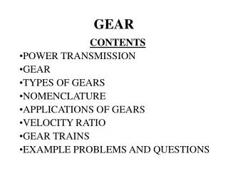
INTRODUCTION • Gear is a rotating machine part having cut teeth or cogs, which mesh with another toothed part in order to transmit torque. • Two or more gears working in tandem called transmission and can produce mechanical advantage through gear ratio • Gear normally mounted on a shaft and transmit rotating motion from one parallel shaft to another
INTRODUCTION • Gears and shafts can interacts: • 1. gear can drive the shaft • 2. shaft can drive the gear • 3. gear can be free to turn the shaft (an idler gear) • Set of gear can • 1. multiply torque and decrease speed • 2. increase speed and decrease torque • 3. transfer torque and leave speed unchanged • 4. to reverse the direction of rotation
Gear Pitch • Gear pitch refers to number of teeth per given unit of pitch diameter and can be calculate by dividing number of teeth with pitch diameter of the gear .
Type of Gear 1. Spur gears – straight cut gears. Consist of cylinder or disk with teeth projecting radially and only meshed together correctly only if fitted to parallel axles. • Advantage • - simplest gear design • - often use for the reverse gear • Disadvantage • - clicking noise occurs as teeth contact each another • - only one tooth in full contact at a time • - at high speed clicking become a constant whine
Type of Gear 2. Helical Gear – leading edges of teeth not parallel to the axis of rotation (set at an angle). Since gear is curved the angle causes tooth shape to be segment of helix. Helical gears can be meshed in a parallel or crossed orientations. • Advantage • - very strong gear • - run quietly than spur gear • - can be either righthanded or lefthanded.
Type of Gear • disadvantage • - helical gear teeth cause gear to move fore (axial thrust) on a shaft.
Gear Train • create large gear ratio, gears are often connected together in gear train • When two gears meshed together, one rotates in the opposite direction as the other • If an external gear is meshed with an internal gear, both rotate in the same direction
Idler Gear • gear that placed between drive gear and driven gear • transfer motion from drive gear to driven gear without changing the direction of rotation
Torque, Speed & Power • Torque is a twisting force commonly expressed in pound-feet (lb-ft) or Newton-meters (N-m). Gears apply torque much like a wrench does; each tooth of a gear is actually a lever. • Gear with a 2-foot radius, applying a force of 10 pounds to one gear tooth exerts 20 lb-ft of torque on the centre of the shaft to which the gear attaches.
Torque, Speed & Power • Torque curve of an engine shows how much torque is available at different points within a range of engine speeds. • Torque multiplication must be provided between the crankshaft and drive axles to enable a vehicle to begin moving from standstill and to accelerate at low speeds. • Once engine RPM rises beyond torque peak, change in gear ratio brings engine speed back within the most efficient torque producing range.
Torque & Speed Relation • Torque and speed have an inverse relationship: • 1. as one goes up, the other goes down. • 2. With constant input speed, transmission torque decreases as output speed increases. • 3. The opposite also applies assuming a constant input speed, transmission torque increases as output speed decreases.
Why engine need Torque • When vehicle move on level ground, engine torque is enough to keep vehicle moving
Why engine need Torque • Output torque from engine increases proportionally with engine rpm to a certain point, this is a factor that greatly affects drivetrain design since very little torque is developed at engine speeds below 1000 rpm. • Modern engine begins producing usable torque at about 1200 rpm and peak torque at about 2500 to 3000 rpm
Why engine need Torque • When vehicle car on steep hill / grade, original amount of torque is insufficient, so it is necessary to increase torque by means of a torque converter or multiplier. • Twisting force of engine is multiplied through use of transmission gears
Torque Multiplication • Levers and fulcrum can be used to increase or multiply torque.
Torque Multiplication • A wheel too heavy for a person to turn by muscle power alone, it turns easily when that same person uses a lever and fulcrum to multiply the applied force. • The force, or torque, increases at one end, but the lever must be moved a greater distance at the opposite end to obtain the increase in force. Either distance or speed must always be given up in order to increase, or multiply, torque.
Torque Multiplication • With weight 200 lbs. and want to lift 4,000 lbs. the required distance from fulcrum is 20 ft. • In order to raise weight short distance, it is mandatory to depress end of lever a distance 20 times as much as the distance the weight has been raised.
Torque Multiplication • note that as engine torque increased, speed with which weight (car) moved becomes slower. • as engine torque multiplication increases, vehicle road speed will decreased. • If engine speed remains constant and torque is multiplied, engine will lift more weight but in longer time. • If engine speed remains constant and torque is reduced, it will lift less weight but will lift it faster.
Torque Multiplication Through Gears • Gears can be used in the same way as levers to multiply torque. When two gears of the same diameter are meshed, the driven gear will turn at the same speed as the drive gear. Since there is no difference in speed, there is no difference in torque between the two gears. • Principle of gear torque multiplication is the larger the driven gear in relation to driving gear, the greater torque multiplication. As torque is increased, driving gear must turn more time to turn driven gear once.
Torque Multiplication Through Gears • If drive gear is one-third diameter of driven gear, it must rotate three times for each rotation of the larger gear. This means larger gear will turn three times slower than smaller gear. At same time, larger gear will exert three times torque of smaller gear. • When speed decreases, torque increases. Torque multiplication and gear ratios are directly related. When a gear system is in reduction, there is more torque available at the driven gear, but less speed.
Torque Multiplication Through Gears • Principle driving gear tooth is 1 ft. from the center of the shaft. If it were pushing down with a 200 lb. force, the driving tooth would be exerting a 200 ft. lb. push on the tooth of the driven gear. As the driven tooth is 4 ft. from the center of the drive shaft, it would exert an 800 ft. Ib force on the drive shaft.
Gear Ratio • Ratio of the size of two or more gears acting on each other. If a drive gear has 9 teeth and driven gear twice as large as the drive gear then the driven gear will rotate ½ revolution for each revolution of the drive gear
Gear Ratio • Ratios vary from car to car depend on engine horsepower and car weight. • Gear ratios are determined by dividing number of teeth on driven gear by number of teeth on drive gear. • example : 18/9 = 2, therefore the ratio is 2:1
Gear Ratio • Ratio of 2:1 - two revolutions of drive gear will produce one revolution of driven gear. This called reduction, reduction in speed, but increase in torque. • If drive gear has 18 teeth and driven gear 9, there will be an increase in speed and a reduction in torque. This is referred as overdrive. Ratio : 9/18 = 0.5:1. • Ratio always written so that number 1 is to the right of the colon. This represents one turn of the output gear, while the number to the left represents the revolutions of the input
Gear Ratio • To calculate gear ratio in various set of gear • divide the driven (output) gear of the first set by the drive (input) gear of the first set. Do the same for the second set of gears and multiply the answer from the first by the second. mathematical formula driven (A) driven (B) ----------------- x ----------------- drive (A) drive (B)
Reverse Gear Ratio • Reverse gear involve two driving gears and two driven gears • input gear is driver #1 • idler gear is driven # 1 • idler gear is also driver #2 • output gear is driven #2 mathematical formula driven (#1) driven (#2) ----------------- x ----------------- drive (#1) drive (#2) • Reverse gear ratio = driven #2 / drive #1