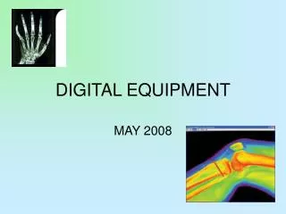
DIGITAL EQUIPMENT
DIGITAL EQUIPMENT. MAY 2008. TERMINOLOGY REVIEW. ARRT CONTENT SPECS 2008. Image Receptors digital image characteristics spatial resolution sampling frequency DEL (detector element size) receptor size and matrix size image signal (exposure related) quantum mottle

DIGITAL EQUIPMENT
E N D
Presentation Transcript
DIGITAL EQUIPMENT MAY 2008
TERMINOLOGY REVIEW ARRT CONTENT SPECS 2008
Image Receptors digital image characteristics spatial resolution sampling frequency DEL (detector element size) receptor size and matrix size image signal (exposure related) quantum mottle SNR (signal to noise ratio) or CNR (contrast to noise ratio) Digital Systems electronic collimation grayscale rendition or look-up table (LUT) edge enhancement/ noise suppression contrast enhancement system malfunctions (e.g., ghost image, banding, erasure, dead pixels, readout problems, printer distortion) ARRT SPECS - DIGITAL
ARRT SPECS - DIGITAL • Image Display • viewing conditions (i.e., luminance,ambient lighting • spatial resolution • contrast resolution/dynamic range • DICOM gray scale function • window level and width function • Image Acquisition and Readout • PSP (photo-stimulable phosphor) • flat panel detectors • (direct and indirect) • Noise • Acceptable Range of Exposure • Exposure Indicator Determination • Gross Exposure Error • Image Degradation (mottle, light or dark, low contrast)
ARRT SPECS - DIGITAL • Recognition of Malfunctions • Digital Image Receptor Systems • Digital artifacts • (grid lines, Moiré effect or aliasing) • maintenance (e.g., detector fog) • ( non-uniformity, erasure)
ARRT SPECS - DIGITAL • PACS • HIS (hospital information system) - work list • RIS (radiology information system) • DICOM • Workflow (inappropriate documentation, lost images, mismatched images, corrupt data) • windowing and leveling
Key Terms • Computed radiography • DICOM (digital imaging and communications in medicine) • Digital imaging • Digital radiography • Direct capture DR • Indirect capture DR • PACS • Teleradiology
Digital Radiography Direct Capture Indirect Capture Computed Radiography (CR) - PSL Direct-to-Digital Radiography (DDR)-Selenium Direct-to-Digital Radiography Silicon Scint. Laser Scanning Digitizers
Image Acquisition and Readout • PSP (photo-stimulable phosphor) • flat panel detectors • (direct and indirect)
Computed Radiography • Uses storage phosphor plates • Uses existing equipment • Requires special cassettes • Requires a special cassette reader • Uses a computer workstation and viewing station and a printer
Computed Radiography • Storage phosphor plates are similar to intensifying screens. • Imaging plate stores x-ray energy for an extended time. • Process was first introduced in the United States by Fuji Medical Systems of Japan in 1983. • First system used a phosphor storage plate, a reader, and a laser printer.
Imaging Plate • Construction • Image recorded on a thin sheet of plastic known as the imaging plate • Consists of several layers:
Cassette and Imaging Plate • Cassette contains a window with a barcode label or barcode sticker on the cassette. • Label enables technologist to match the image information with the patient-identifying barcode on the exam request.
Using the Laser to Readthe Imaging Plate • The light collection optics direct the released phosphor energy to an optical filter and then to the photodetector. • Although there will be variances between manufacturers, the typical throughput is 50 cassettes per hour. • Some manufacturers claim up to 150 cassettes per hour, but based on average hospital department workflow, 50 cassettes per hour is much more realistic.
Process up to 101 cassettes an hour. • Handle 16 cassettes at one time: up to 8 queued for processing, and 8 erased and ready for new imaging studies. • Cassette is ready to reuse in 40 seconds.* • Review an image in 34 seconds at a Kodak DirectView remote operations panel.* • “Drop-and go” workflow virtually
Based on proven DirectView CR 850 system design ·Process up to 62 35 x 43 cm plates an hour ·Small footprint size of 25 x 29 inch (63.5 x 73.6 cm
Digital Radiography • Cassetteless system • Uses a flat panel detector or charge-coupled device (CCD) hard-wired to computer • Requires new installation of room or retrofit
Digital Radiography • DR is hard-wired. • DR is cassetteless. • Detectors are permanently enclosed inside a rigid protective housing. • Thin-film transistor (TFT) detector arrays may be used in direct- and indirect-conversion detectors.
Digital Radiography • Two types of digital radiography • Indirect capture DR • Machine absorbs x-rays and converts them to light. • CCD or thin-film transistor (TFT) converts light to electric signals. • Computer processes electric signals. • Images are viewed on computer monitor.
Digital Radiography • Direct capture DR • Photoconductor absorbs x-rays. • TFT collects signal. • Electrical signal is sent to computer for processing. • Image is viewed on computer screen.
Digital Radiography • DR used CCD technology developed by the military and then used TFT arrays shortly after. • CCD and TFT technology developed and continues to develop in parallel. • No one technology has proved to be better than the other.
Flat-Panel Detectors • Consist of a photoconductor • Amorphous selenium • Holds a charge on its surface that can then be read out by a TFT
Direct Conversion • X-ray photons are absorbed by the coating material. • Photons are immediately converted into an electrical signal. • The DR plate has a radiation-conversion material or scintillator.
Direct Conversion DR Scintillator • Typically made of amorphous selenium • Absorbs x-rays and converts them to visible photons • Converts photons to electrical charges • Charges stored in the TFT detectors
Indirect Conversion • Similar to direct detectors in that the TFT technology is also used • Two-step process: • X-ray photons are converted to light. • Light photons are converted to an electrical signal. • A scintillator converts x-rays into visible light. • Light is then converted into an electrical charge by photodetectors such as amorphous silicon photodiode arrays or charge-coupled devices, or CCDs.
Indirect Conversion • More than a million pixels can be read and converted to a composite digital image in under a second.
Comparison of Film to CR and DR • For conventional x-ray film and computed radiography (CR), a traditional x-ray room with a table and wall Bucky is required. • For DR, a detector replaces the Bucky apparatus in the table and wall stand. • Conventional and CR efficiency ratings are about the same. • DR is much more efficient, and image is available immediately.
Comparison of Film to CR and DR • CR • A storage phosphor plate is placed inside of CR cassette. • Most storage phosphor plates are made of a barium fluorohalide. • When x-rays strike the photosensitive phosphor, some light is given off. • Some of the photon energy is deposited within the phosphor particles to create the latent image. • The phosphor plate is then fed through the CR reader.
Comparison of CR and DR • CR, continued • Focused laser light is scanned over the plate, causing the electrons to return to their original state, emitting light in the process. • This light is picked up by a photomultiplier tube and converted into an electrical signal. • The electrical signal is then sent through an analog-to-digital converter to produce a digital image that can then be sent to the technologist review station.
Comparison of CR & DR • DR • No cassettes are required. • The image acquisition device is built into the table and/or wall stand or is enclosed in a portable device. • Two distinct image acquisition methods are indirect capture and direct capture. • Indirect capture is similar to CR in that the x-ray energy stimulates a scintillator, which gives off light that is detected and turned into an electrical signal. • With direct capture, the x-ray energy is detected by a photoconductor that converts it directly to a digital electrical signal.
Amorphous Silicon Detector • The light photons are then converted into an electric charge by the photodiode arrays. • Unlike the selenium-based system used for direct conversion, this type of indirect-conversion detector technology requires a two-step process for x-ray detection. • The scintillator converts the x-ray beams into visible light, and light is then converted into an electrical charge by photodetectors, such as amorphous silicon photodiodes
Cesium Iodide Detectors • A newer type of amorphous silicon detector uses a cesium iodide scintillator. • The scintillator is made by growing very thin crystalline needles (5 µm wide) that work as light-directing tubes, much like fiber optics. • This allows greater detection of x-rays, and because there is almost no light spread, there is much greater resolution.
Cesium Iodide Detectors • These needles absorb the x-ray photons and convert their energy into light, channeling it to the amorphous silicon photodiode array. • As the light hits the array, the charge on each of the photodiodes decreases in proportion to the light received.
Charge-Coupled Devices • The oldest indirect-conversion DR system is based on CCDs. • X-ray photons interact with a scintillation material, such as photostimulable phosphors, and this signal is coupled or linked by lenses or fiber optics, which act like cameras.
Charge-Coupled Devices • These cameras reduce the size of the projected visible light image and transfer the image to one or more small (2 to 4 cm2) CCDs, which convert the light into an electrical charge. • This charge is stored in a sequential pattern and released line by line and sent to an analog-to-digital converter.
Charge-Coupled Devices • Even though CCD-based detectors require optical coupling and image size reduction, they are widely available and relatively low in cost.
Summary • There are two types of cassetteless digital imaging systems: direct and indirect. • Direct sensors are TFT arrays of amorphous silicon coated with amorphous selenium. • Direct sensors absorb x-ray photons and immediately convert them to an electrical signal.
Summary • Indirect-conversion detectors use a scintillator that converts x-rays into visible light, which is then converted into an electrical charge. • CCDs act as miniature cameras that convert light produced by x-ray interaction with photostimulable phosphors into an electrical charge.
Image Display • viewing conditions (i.e., luminance,ambient lighting • DICOM gray scale function • window level and width function • spatial resolution • contrast resolution/dynamic range
MONITOR RESOLUTION • DICOM gray scale function • window level and width function
Depending on modalities such as CT, CR, MRI, resolution requirements can range from 1.3 megapixels to 5 megapixels. Generally, 3 megapixel and higher class displays are used for softcopy interpretation. Where higher accuracy and a subtle reproduction of grayscale are critical in applications such as mammography imaging, 5 megapixel resolution is required.
A photometer to a monitor screen in a check of the monitor's conformance with the DICOM Grayscale Standard Display Function. DICOM gray scale functionwindow level and width function