Download
1 / 27
270 likes | 372 Views
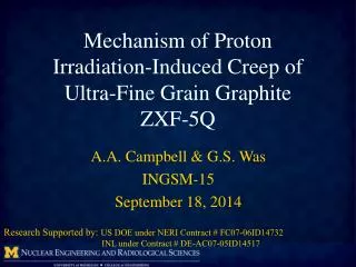
Investigation of Proton Irradiation-Induced Creep of Ultrafine Grain G raphite. Anne A. Campbell & Gary S. Was University of Michigan Research Supported by US DOE under NERI Contract # FC07-06ID14732 And INL under Contract # DE-AC07-05ID14517. Outline. Objective Background

E N D
Investigation of Proton Irradiation-Induced Creep of Ultrafine Grain Graphite Anne A. Campbell & Gary S. Was University of Michigan Research Supported by US DOE under NERI Contract # FC07-06ID14732 And INL under Contract # DE-AC07-05ID14517
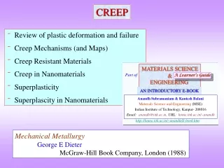
Outline • Objective • Background • Experimental Setup & Procedure • Research Approach • Results • Comparison with Neutron Data • Summary
Objective • Investigate the irradiation-induced creep of ultra-fine grain graphite • Study the effect of stress, dose rate, and temperature on creep rate • Compare results with neutron irradiation-induced creep work
Background • Using POCO grade ZXF-5Q • Particle size < 1 µm • Density 1.78g/cm3 • Tensile Strength 79 MPa • Anisotropy < 1.03 BAF • Young’s Modulus 14.5 GPa • Using 3 MeV protons for radiation damage and heating • 3 MeV used to keep damage rate ratio from front to back of sample below 1.5 (from SRIM calculations) • 70 µm maximum sample thickness • Final sample size 3mm x 0.07 mm x 33 mm (cut via EDM) POCO Grade ZXF-5Q Data sheet.
Experiment – Irradiation Chamber Campbell, A.A. and G. S. Was, Journal of Nuclear Materials, 433 (2013) 86-94.
Camera Laser Analysis Program Sample Laser Speckle Extensometer (LSE)
Irradiation Creep Experimental Procedure • Assemble stage, test heater, mount samples, apply and remove tensile load on bench-top, align and test beam apertures • Assemble chamber on beam-line, insert load, insert stage, align LSE, apply load to sample, seal top port, pump out chamber, start LSE DVRT and Stage data collection, condition vacuum, align 2D thermal imager start temperature collection • Obtain desired proton current in Faraday cup, increase beam scanner to wider than necessary, apply beam to samples, balance beam one apertures, narrow scanner width until desired temperature is achieved, set alarms for temperature and dose rate monitoring and control • Analyze LSE and DVRT data to determine linear fit and 95% CI of slope, continue at same conditions until 95% CI < 1% of the slope or desired final dose is achieved, change to other conditions or end experiment • Insert Faraday cup, cool system to room temperature, remove stress from sample, vent vacuum chamber, remove stage, remove samples from stage, put individual samples in boxes labeled with all relevant irradiation information
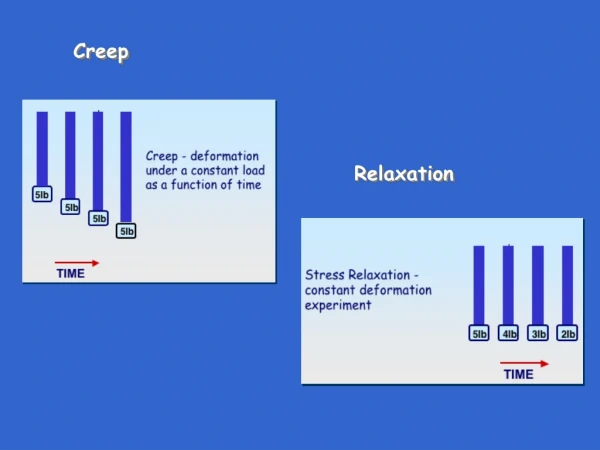
Irradiation Creep Experimental Conditions • Applied tensile stress (1000ºC, 1.15x10⁻⁶dpa/s) • 5 MPa, 10 MPa, 20 MPa, 40 MPa • Dose Rate (700ºC, 20MPa) • 2.95x10⁻⁷dpa/s to 5.51x10⁻⁷dpa/s • Temperature (20MPa, variable dose rate) • 700ºC, 900ºC, 1000ºC, 1100ºC, 1200ºC • Two samples used for each experiment, one with stress and one without stress • Residual stress from EDM machining resulted in curvature of the unstressed sample
Stress Dependence Comparison Gray, Carbon, 11, (1973) 183 Oku et al., JNM, 152, (1988) 225 Oku et al., JNM, 172, (1990) 77
Dose Rate Comparison Veringa and Blackstone, Carbon, 14, (1976) 279. Oku et al., JNM, 152, (1988) 225 Oku et al., JNM, 172, (1990) 77
Accumulated Dose Comparison Neutron Data for H-451 from: Burchell, T.D., JNM, 381, (2008) 46.
Temperature Comparison Veringa and Blackstone, Carbon, 14, (1976) 279. Burchell, T.D., JNM, 381, (2008) 46. Gray et al., Carbon, 5, (1967) 173 Kelly and Burchell, Carbon, 32, (1994) 119. Mitchell et al., Nuclear Energy, 41, (2002) 63 Oku et al., JNM, 152, (1988) 225 Oku et al., JNM, 172, (1990) 77 Perks and Simmons, Carbon, 1, (1964) 441. Perks and Simmons, Carbon, 4, (1966) 85.
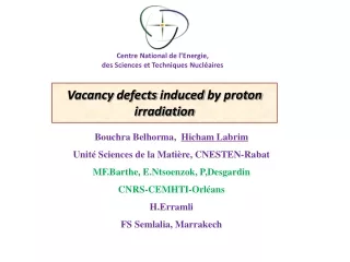
Possible Source of Discrepancy • Protons provide both displacement damage and heating from electronic excitation • Damage comes from PKA interaction • Fundamentally similar PKA interaction within material • Neutron irradiations have both neutron and γ-rays interacting with material
γ – Ray Effects • Work in Russia • Examined effect of Radiation Composition Factor (RCF=ϕn/ϕγ) on Turn-around dose (Fcrit) • Use equation to determine effective temperature (i.e. temperature without γ-rays) BOR-60 (4) MR (0.13) SM-2 (0.1) Nikolaenkoet al., Atomic Energy, 87, (1999) 480.
Neutron Results – H-451 Burchell, T.D., "Neutron Irradiation Damage in Graphite and Its Effects on Properties", Presented at International Carbon Conference CARBON 2002, Beijing, China, September 15-20, 2002.
Discussion of Analysis • Russian researchers proposed that γ-rays interact and produce fast electrons that stimulate diffusion processes • Recent work in China investigated the effects of γ-rays, on graphite, at room temperature • Shows that γ-rays can increase graphitization of graphite at room temperature • Possible thatγ-rays are annealing damage as it is being caused by neutrons in-reactor, effectively reducing the # of defects available to assist with driving creep Li, B. et al., Carbon, 60, (2013) 186. Xu, Z. et al., Materials Letters, 63, (2009) 1814.
Summary • Proton Irradiation-Induced creep experiments preformed on POCO ZXF-5Q graphite • Investigated stress, dose rate, temperature, and accumulated dose effects on creep behavior • Linear dependence on stress, dose rate, and temperature trends agree with neutron creep measurements • Compliance values for protons factor of 6-10 higher than neutron values • Experimental results suggest creep is driven by defect population and γ-rays reduces the defect population, which reduces creep rate
Investigation of Proton Irradiation-Induced Creep of Ultrafine Grain Graphite Anne A. Campbell & Gary S. Was University of Michigan Research Supported by US DOE under NERI Contract # FC07-06ID14732 And INL under Contract # DE-AC07-05ID14517