Download
1 / 31
310 likes | 464 Views
AFP QUARTIC Fast Timing System James L Pinfold University of Alberta. AFP QUARTIC Timing Group. University of Alberta, University of Texas at Arlington, University of Giessen, SUNY Stoneybrook

E N D
AFP QUARTIC Fast Timing SystemJames L PinfoldUniversity of Alberta
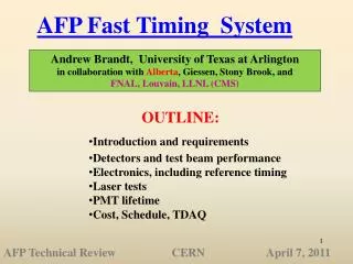
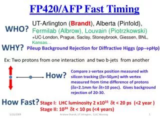
AFP QUARTIC Timing Group • University of Alberta, University of Texas at Arlington, University of Giessen, SUNY Stoneybrook • The primary goal has been to have the AFP timing system fully defined for the AFP Technical Proposal: • The end result should be a system that can obtain 20 ps resolution at an instantaneous luminosity of 1033 and given funding could be built and installed by mid/late 2012, and a second stage system capable of 10 ps or better resolution at an instantaneous luminosity of 1034 and given funding could be built and installed by 2015.
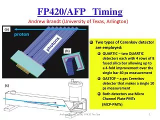
AFP Baseline Timing Plan 30 cm • Two types of Cerenkov detector are employed: • GASTOF – a gas Cerenkov detector that makes a single measurement • QUARTIC – two QUARTIC detectors each with 4 rows of 8 fused silica bar will be positioned after the last 3D-Si tracking station because of the multiple scattering effects in the fused silica. • Both detectors employ Micro Channel Plate PMTs (MCP-PMTs)
The QUARTIC Baseline Detector • Each QUARTIC detector has 4 rows of 8 5mm x 5mm x ≤ ~10 cm long fused silica bars (end-2-end =16 measurements) allowing up to a 4-fold improvement of resolution over that of a single bar • The refractive index of fused silica is ~1.5 ( Cerenkov angle of 50o) • An array of bars is mounted at the Cerenkov angle to minimize the # reflections as the light propagates to the MCP-PMT. • This arrangement is intrinsically rad hard • AFP has been concentrating on developing this detector including the full electronics chain
An early QUARTIC Prototype OR 2) Use longer bars as the light guide PRO: more light CON: more time disp. • Use short bars and • reflective light guide • PRO: Less time dispersion • CON: less light
We are also (in conjunction with Giessen) Testing Fused Silica Fibres as a Replacement for Bars • Tests indicate the we can expect better time resolution with FS fibres (~30% better) – although less total light • Fibres will allow flexible/finer segmentation and also better mapping onto the MCPMT
Excellent time resolution: 20-30 ps or better for 10 pe’s • High rate capability: Imax ~ 3 A/cm2 • Long Lifetime: Q~ 10 to 20 C/cm2 needed at high luminosity • Multi anode: pixel size of ~6 mm x 6mm • Pore Size: 10 m or better • Tube Size: 40 mm round, 1 or 2 inch square • Need to have capability of measurements in different parts of tube between 0-2 ns apart, and in same part of the tube 25 ns apart MCP-PMT Requirements
Micro-channel Plate PMT (MCP-PMT) • Burle/Photonis 64 channel 10 or 25 m pore has been tested extensively with test beam and laser and would be default for first stage except for lifetime issues
Pico-second Test Facility at UTA UTA laser setup: with LeCroy Wavemaster 6 GHz Oscilloscope Test-stand optical system HamamatsuPLP-10 405 nm laser pulser Beam Mode Fiber Mode
Laser Facility Test Results Timing vs. Gain If NPE x Gain ≥ 5 x 10⁵ then timing independent of HV/gain With sufficient amplification there is no dependence of timing on gain Saturation (the reduction in amp). of the output signal due to the busy pores is a local phenomena
Cross-talk • The amount of signal sharing affects ability to measure two adjacent rows/columns independently • As one proton enters some time before the other, the second timing measurement shifts due to cross talk
Cross-talk Results • Tested a prototype Burle Planacon tube using variable length fibers • Examined both row and column effect of spillover signal 100, 250 and 500 ps before the target pulse • About 10% of the pulse is detected in adjacent, empty pixels • Data shows that early light is not significantly affected by later light • Later light mean time is shifted, but is not totally dominated by the early pulse • Late time measurement degrades significantly as Δt increases • Exploring ways to reduce this effect
Beam vs Fiber Fiber timing not as good, but allows us flexibility for some characterization tests
The √N Effect 29 ps 29 ps 23 ps 22ps 16.4 s 16.6 ps • Measure time difference of 4 • separate fibers • (10 pe’s) wrt laser • Note all values less • Than 35 ps due to in • time leakage from neighboring pixels • (29 for edge 22 for middle) • Correct for T0 offset, average and take new time difference: • Get 35/4=17 ps! • Need to verify in test beam 17 ps
Timing – CERN Test-Beam 2008 Npe=(area/rms)2 56.6/1.4=40 ps/ Bar including CFD! Dt • Time difference between two 9 cm quartz bars after the CFD implies a single bar resolution of 40 ps for about 10 pe’s (expected 10 pe’s from simulations)
QUARTIC Efficiency CERN TB (a) (b) Events Shape due to veto counter with 15mm diameter hole Efficiency 6 mm (c) Strip # Use tracking to determine that QUARTIC bar efficiency is high and uniform
CERN/FNAL 2010 Test Beam QUARTIC: • At the 2008 CERN test we got single bar resolution of 40 ps for about 10 PE’s – in 2010 test we are now seeing ~30ps single bar resolution • New quartz bar prototype test (Alberta 8 long-bar prototype), use scope to measure raw signal and compare to laser, pulse height, number of PE’s, timing resolution • 8 channel electronics test AMP->CFD->HPTDC • [sqrt(N) test] study coherent noise effects and 8-channel timing • Compare 25 mm and two 10 mm Burle tubes (single channel & also 8 channel) FIBRE: • Giessen fiber detector with Giessen readout • Repeat for QUARTIC readout • Alberta fiber bundle comparison tests SiPM TESTS ANALYSIS IN PROGRESS
QUARTIC Readout Electronics • Electronics has been tested at the UTA laser facility, the CERN Test beam in 2008 a CERN test beam in 2010 (August) and recently at a test beam at FERMILAB • The latest tests show that this electronics chain works with SiPMT as well as MCPMT readout
Electronics - Responsibilities • Alberta: has upgraded Louvain CFD and developed HPTDC board • Goals: • Complete design of a 3 HPTDC chip, 8 channel HPTDC board based on successful one chip design (due to occupancy issues only 4 channels available/chip, and one of these is used for reference timing, so a 3 chip board gives 8+1 channels) • Documentation + further system tests, including connections with ROD • Radiation tests of CFD + HPTDC electronics • Stony Brook – Goals: • Tests of chain PULSER==>Preamp==>CFD • SPICE model of the chain PreAmp==>CFD==>Trigger • Tests of trigger circuitry • Detailed design of PreAmp PCB • Detailed design of Trigger circuitry
QUARTIC Electronics – the CFD • Mini-module approach tuned LCFD mini-module to Burle and Hamamatsu rise times; • 12 channel NIM unit good performance : <10 ps resolution for ≥ 4 PE’s • Remote control for threshold ZX60 3 GHz amp
QUARTIC Electronics – the HPTDC • 12 ps resolution obtained with pulser • Successfully tested at UTA laser test stand with laser /10 m tube/ZX60 amp/CFD - 13.7ps resolution obtained with CFD • ~30 ps resolution obtained with real pulses at test beam
HPTDC Buffering Structure • The 6 mm pixel (PMT) which is closest to beam, would see max. hit rate is 15 MHz - the time interval between hits is ~67 ns;
Simulation Results – Loss Rate Study used HPTDC Verilog model Loss rate in the channel buffer, with the following conditions: Logic core clock = 40MHz, Only input channel 0 is connected; Loss rate in the channel buffer, with the following conditions: Logic core clock = 80MHz, Only input channel 0 is connected;
Buffering Test Results • Standard version of HPTDC chip could work with a core clock frequency up to 80 MHz • A special speed graded version of HPTDC chip could work with core clock of 160 MHz. • RMS resolution is not affected when running with 80MHz clock. • But power consumption is increased. • Need to use 2 channels “ganged” to take the maximum rate • 8 channel board 4 channel board
The Lifetime Challenge • Lifetime due to photocathode damage from positive ions is proportional to extracted charge: • Using a fiber detector we would accumulate 10-20 C/ cm2 /yr (assuming 5x10⁴ gain) at the highest lumi • This is a factor of ~20 more than typical tube lifetime!
What To Do • We are pursuing the development of a tube with at least ~20 times longer lifetime, the avenues of improvement are: • Including an ion barrier (Nagoya solution) – giving a factor of 5 6 or more (latest SL10 results?) • Z stack design gives a factor of ~10 improvement (NIM A598,160,09) • Arradiance coated MCP’s: promises a factor of 10 or more lifetime improvement. • UTA have a funded Small Business Proposal with Arradiance and Photonis (starting Jan. 2011) to develop a long life MCP-PMT using Arradiance coated MCP's • Various combinations of these factors are possible and should give multiplicative improvement factors
Conclusion • We have developed a fast timing system for AFP that seems to be capable of ~10 ps resolution • Work in progress: • final optimization of detector (quartz fibers could lower maximum rate by 2-3 by more sensible binning) • Developing final (3 chip) HPTDC board (Alberta) and trigger circuit (Stony Brook) • Test beam and laser tests • Developing and testing long-life MCP-PMT (new funding) • Evaluating radiation tolerance of all components and upgrading as needed • SiPm alternative Write up results for Technical Proposal
QUARTIC HPTDC Buffering Study used HPTDC Verilog model & measurement, simulation details: • Hit rate: • The number of interested interactions at bunch crossing (40 MHz) is on (Poisson) average of 25, from which each has a 3 % chance to hit QUARTIC detector, this gives a rate of 40 MHz *25*3% = 30 MHz; • The 6 mm pixel (PMT) which is closest to beam, would see max. hit rate is 30/2 = 15 MHz - the time interval between hits is ~67 ns; • A hit (track) strikes all input channels at the same time. The input channel the min. Dt between hits - 25 ns. • Trigger rate: • ATLAS L1 trigger rate 100 KHz, with a trigger latency of 2.5 ms; • The time interval between triggers is on an exponential distribution; • The minimum spacing between triggers is 25 ns Conclusions Triggering Timing Manchester Forward Physics James Pinfold