Download
1 / 22
300 likes | 1.06k Views
Electrons. Thermionic Emission Deflection of Electrons in Electric Field Deflection of Electrons in Magnetic Field Determination of e/m Cathode Ray Oscilloscope. Thermionic Emission (1).

E N D
Electrons Thermionic Emission Deflection of Electrons in Electric Field Deflection of Electrons in Magnetic Field Determination of e/m Cathode Ray Oscilloscope
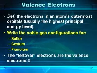
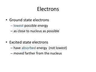
Thermionic Emission (1) • When a metal is heated sufficiently, its free electrons gain enough kinetic energy to leave the metal. This process is called thermionic emission.
Thermionic Emission (2) • In practice, thermionic emission is caused by heating a filament of metal wire with an electric current.
1 electron-volt = J Thermionic Emission (3) • The work done on each electron from the filament is W = eV where V is the p.d. across the filament and the anode. • Electron-volt The electron-volt is an amount of energy equal to the work done on an electron moved through a p.d. of 1V.
Properties of Electron Beams (Cathode rays) • Cathode rays travel in straight lines. • Cathode rays can cause fluorescence. • Cathode rays can be deflected by electric field and magnetic field. • Cathode rays may produce heat and X-rays. • Cathode rays can affect photographic plates.
+ d - Deflection of Electrons in a Uniform Electric Field (1) • Consider an electron beam directed between two oppositely charged parallel plates as shown below. • With a constant potential difference between the two deflecting plates, the trace is curved towards the positive plate.
where E = electric field strength, V = p.d. between plates, d = plate spacing. p Deflection of Electrons in a Uniform Electric Field (2) • The force acting on each electron in the field is given by
Deflection of Electrons in a Uniform Electric Field (3) • The vertical displacement y is given by This is the equation for a parabola.
Deflection of Electrons in a Uniform Magnetic Field (1) • The force F acting on an electron in a uniform magnetic field is given by Since the magnetic force F is at right angles to the velocity direction, the electron moves round a circular path.
Deflection of Electrons in a Uniform Magnetic Field (2) • The centripetal acceleration of the electrons is Hence which gives
Determination of Specific Charge - e/m J. J. Thomson
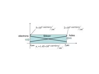
× × × × × × × × × × × × × × × × × × × × × × × × × × × × × × × × × × × × × × × × Electron gun F=Bev v r Determination of Specific Charge Using a Fine Beam Tube (1) • The principle of the experiment is illustrated by the diagram below.
(For an electron moving in a uniform magnetic field) Since Determination of Specific Charge Using a Fine Beam Tube (2) and the kinetic energy of the electron provided by the electron gun is Where V is the anode voltage.
So C/kg Determination of Specific Charge Using a Fine Beam Tube (3) Rearrange the equation gives The value of the specific charge of an electron is now known accurately to be
+ × × × × × × × × × × × × × × × × × × × × × × × × × × × × × × × × × × × × v - Thomson’s e/m Experiment (1) Thomson’s apparatus for measuring the ratio e/m
Thomson’s e/m Experiment (2) • A beam of electron is produced by an electron gun with an accelerating voltage V. • The electron beam is arranged to travel through an electric field and a magnetic field which are perpendicular to each other. • The apparatus is set-up so that an electron from the gun is undeflected.
eE v i.e. Bev On the other hand, Thomson’s e/m experiment (3) • As the electron from the gun is undeflected, this gives Combining the equations, we get
Cathode Ray Oscilloscope (CRO) • The structure of the cathode ray tube
Uses of CRO • An oscilloscope can be used as 1. an a.c. and d.c. voltmeter, 2. for time and frequency measurement, 3. as a display device.
Lissajous’ Figures (1) • Lissajous’ figure can be displayed by applying two a.c. signals simultaneously to the X-plates and Y-plates of an oscilloscope. • As the frequency, amplitude and phase difference are altered, different patterns are seen on the screen of the CRO.
Lissajous’ Figures (2) Same amplitude but different frequencies
In phase π/2 π 3π/2 In phase π /4 3π/4 5π/4 7π/2 Lissajous’ Figures (3) Same frequency but different phase http://surendranath.tripod.com/Lissajous/Lissajous.html