Download

1 / 23
230 likes | 390 Views
Can Bottom Snap-through. MSC.Patran 2005 r2 MSC.Marc 2005 r2. Estimated Time for Completion: ~35min Experience Level: Lower. Topics Covered. Topics covered in Modeling Importing Geometry file with FEA data. Neutral format (.out) Creating Material Properties using Fields option.

E N D
Can Bottom Snap-through MSC.Patran 2005 r2 MSC.Marc 2005 r2 Estimated Time for Completion: ~35min Experience Level: Lower
Topics Covered • Topics covered in Modeling • Importing Geometry file with FEA data. • Neutral format (.out) • Creating Material Properties using Fields option. • Specify the input data that represent the stress-strain relationship. • Verifying Element Normal • Shell element layers are dependent on the element direction • Topic covered in Analysis • Applying Large Displacement/Large Strains Analysis. • Applying Modified Rik’s/Ramm Method • Topics covered in Review • Creating XY plots • Load vs. Displacement plot • Strain Energy vs. Time plot • Animations • Increment based animation • Time based animation
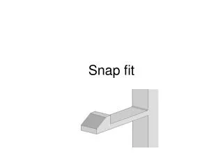
Problem Description • This example demonstrates the nonlinear analysis of the bottom of a 3D aluminum container under given internal pressure. The configuration of the bottom and the critical pressure leads to a snap-through problem. Pressure
Problem Description • Given Parameters • Aluminum can • Dimensions • Thickness of the shell=0.025 in • Diameter of the can= 2.61 in • Material properties • Young’s Modulus=11E6 psi • Poisson’s ratio=0.3 • Simplifying the problem • To apply the axisymmetric condition, the rotation at the center of the bottom is fixed
Goal • Find the critical pressure leading the snap-through phenomenon. • Find the location and value of the maximum stress during the loading and unloading processes. • Plot the Load vs. Displacement, and Strain Energy vs. time.
Expected Results • Deformation Increasing Pressure Time 0.01.0 Decreasing Pressure Time 1.02.0 Snap-through
Create Database file and Import Geometry • Create a New Database file called ‘can_snapthrough.db’ • Use Marc as the analysis Code • Import the Neutral Geometry file called ‘canbottom.out’, and Node and element information will be imported. Imported elements and nodes
Elements • Verify the Shell Element Normal • This is required to know the layer information. • The top layer of the element is numbered as Layer 1. Layer 5 Layer 1
Boudary Condtions Fixed_x • Displacement Constraints • Fixed_x • This will fixed the displacements of the cut surface, however in-plane motion of the surface should be allowed. • Fixed_sym • This will symplify the problem. Unexpected buckling shape will be eliminated. • Pressure • Pressure_in • Loading condition • Pressure_zero • Unloading condition Fixed_sym Pressure_in Pressure_zero
Fields • Stress-strain curve • Plastic material property is defined as a table.
Materials • Elastic model • Aluminum • Elastic Modulus: 11e6 psi • Possion’s ratio: 0.3 • Plastic model • Use the stress-strain curve defined in the previous slide.
Properties • Element Properties • 2D Thin Shell • Material: Aluminum • Thickness 0.025in
Load Cases • Loading • Name: LoadPressure • Apply following three BCs/Load • Fixed_sym • Fixed_x • Pressure_in • Unloading • Name: UnloadingPressure • Apply following three BCs/Load • Fixed_sym • Fixed_x • Pressure_zero LoadPressure UnloadPressure
Analysis • Two Load Steps • Loading • Name: PressureStep • Load Case selected: LoadPressure • Unloading • Name: UnloadingStep • Load Case selected: UnloadPressure • Solving Options • Large Displacement/Large Strain • Loads Follow Deformations • Adaptive Arc Length method • Use Modifed Riks/Ramm method • Use default options for all others • Required nodal results • Displacement, Rotation, Reaction Force, and External Force
Review Results • Select the reference information • Reference nodes to review the displacement and stress results • Reference increment to compare the results based on time (load factor) and increment (solving step) Reference increments for Loading and unloading results: Select the increment resultswith the time increasing. Reference node for the displacement axis Reference nodes for the von-Mises stress
Results loading Snap-through At time=0.74 unloading Based on the increasing time(load) Based on the increment(solving step) • Load applied vs. displacement Curve • Snap-through information can be found by plotting the results with the increasing time. • The critical load leads the snap-through is about 370 psi at time=0.74(=500psi x 0.74)
Results Snap-through Based on the increasing time(load) Based on the increment(solving step) • Plastic Strain Energy vs. Time • Plastic Strain Energy is dramatically increased at the critical load (or time) • It does not changed during the unloading step. So there is only elastic deformation in the step. loading unloading
Results Snap-through Based on the increasing time(load) Based on the increment(solving step) • Elastic Strain Energy vs. Time Elastic Deformation loading unloading
Results • von Mises Stress vs. Time • Use the reference nodes for the von Mises Stress. • Maximum von Mises occurs after the loading step and it is about 0.1 MPa • Locate the maximum stress by plotting on the geometry (Next slide) Snap-through Maximumstress Plastic Deformation loading unloading
Results (Stress: von Mises) • Stress at layer 1 (inside) • Stress at layer 5 (Outside) Max=0.101 psi Max=0.104 psi
Further Analysis (Optional) • Remove the axisymmetric condition (fixed rotation) from the node at the cetner. Find the difference from the current analysis. • For further simplification, use line elements and the axisymmetric condition and compare the results to the one with shell elements.