Packaged Inkjet-Printed Flexible Supercapacitors
220 likes | 414 Views
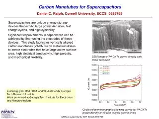
Packaged Inkjet-Printed Flexible Supercapacitors. Matthew Ervin (ARL), Linh Le (SIT), and Woo Lee (SIT). Flexible Supercapacitors for Munitions. Description of Application: Flexible printed supercapacitors for storing energy to power flexible munition electronics

Packaged Inkjet-Printed Flexible Supercapacitors
E N D
Presentation Transcript
Packaged Inkjet-Printed Flexible Supercapacitors Matthew Ervin (ARL), Linh Le (SIT), and Woo Lee (SIT)
Flexible Supercapacitors for Munitions • Description of Application: • Flexible printed supercapacitors for storing energy to power flexible munition electronics • POC: Brian Fuchs & Jim Zunino • Email address: brian.edward.fuchs@us.army.mil james.l.zunino.civ@mail.mil • Important Specifications: • Stores >3 mJ at 3 V • Survive 50+ kGs, 1000 rpm • Flexible • Printable • Benefits Anticipated: • Enable flexible circuits • Reduced cost • Manufacture on demand • Reduced Obsolescence • Improved volume utilization/increased leathality • Rapid prototyping/Mission tailored
Thin-film Supercapacitors for Integration with Uniforms and Equipment Description of Application: Thin-film supercapacitors employing ionogel electrolytes to be integrated in parallel with batteries in uniforms and equipment POCs: Stephanie Flores Zopf Natalie Pomerantz Email addresses: stephanie.f.zopf.civ@mail.mil natalie.l.pomerantz.civ@mail.mil • Important Specifications: • Energy density > 0.5 kJ/m2, > 0.5 kJ/kg • Conductivity = 1 mS/cm • Capacitance = 1µF/cm2 • Electrochemical window = 2.5 V • Long term stability over charge/discharge cycles • Mechanically flexible and conformable • Lightweight • Benefits Anticipated: • Size, weight and power savings • Environmentally safer than electrolytic supercapacitors • Increased reliability over current electrolytic capacitors
Energy Storage Why Supercapacitors? • Supercapacitors store charge by the adsorption of ions onto the electrodes using an electric field. Since there is no dielectric, the voltage must remain low enough that there is no charge transfer or electrochemical breakdown of the electrolyte. Capacitance is proportional to accessible surface area. • Advantages: • Stable performance • Higher specific power (~100x batteries) • Millions of charge/discharge cycles • Rapid charge and discharge times • Efficiencies (98%) • Perform well at extreme temperatures • Safety • Shelf-life • Challenges: • Lower energy densities than batteries • Limited voltage rating on individual cells: • ~1 V for aqueous electrolytes and • ~3 V for organic electrolytes. • Voltage varies with charge • Rigid Packaging • Slow response <1Hz vs other capacitor types • Self-discharge Supercapacitor vs. Electrolytic
Capacitor Types Ragone Plot of Electrochemical Devices Dielectric Electrolytic Electrochemical Double Layer cathode dielectric Al foil Al foil separator anode ‘ electrolyte permittivity Aqueous 1V Organic 2.7V Ionic liquid >3.5V Dielectric strength Ta 50V Al 500V Highest power/frequency Lowest energy Thicker dielectric yields higher voltage, but volumetric energy density unchanged Lower power/frequency More energy Lowest power/frequency Highest energy
Graphene SupercapacitorRationale • Goal: • To increase power and energy density of supercapacitors using graphene CNT/G Rationale: • Graphene has the highest surface area which correlates to capacitance. • 2630 m2/g, external surface area (20uF/cm2 yields 550F/g theoretical) • Graphene is highly conductive which improves power performance. • Carbon has a very good electrochemical window. • The mechanical properties of graphene will enable flexible/conformal supercapacitors. • Graphene oxide makes good solutions, and it is readily reduced. • <$50/kg anticipated in 3 years for graphene.
Flexible Device Component Choices and Issues • Current Collector • Graphene Ink/Printing • Binder(less) • Separator(less) • Electrolyte • Substrate/Package
Substrate/Packaging Material Kapton: Stable to 400oC – facilitates metal ink sintering Good dielectric properties Low outgassing But… Permeable to water, oxygen – electrolyte degradation Use metallization to improve hermetic sealing Not directly heat sealable FEP: Enables heat sealing – flows during sealing (350oC) Chemically inert But… Adhesion of printed features? Unstable substrate when sealing Permeable to small molecules, e.g. CO2
Packaging Permeability AN/thick Kapton/FEP Kapton permeability2.xls IL/thick Kapton/FEP PC/thick Kapton H2O/thick Kapton/Al tape H2O/thick Kapton/FEP H2O/thin Kapton H2O/thin Kapton/FEP
Inkjet Printing Graphene Oxide IR Heat Lamp Print Head • Suspension Stable, Hydrophilic Graphene Oxide (GO) in Water (2mg/ml), no surfactant N Substrate D D • Inkjet Printing Attributes • Micropatternable at 50 um resolution • Additive, net-shape manufacturing with minimum nanomaterial use and waste • Scale-up and integration readiness with rapidly emerging printed electronics Dreyer el al., Chem. Soc. Rev., 2010, 39, 228-240
Ink Preparation • Concentration (2mg/ml) • Less aggregation and nozzle clogging, but requires more printing • Solvent • Using water with graphene oxide, pvdf not soluble in water • Could use N-methyl pyrrolidone with graphene and pvdf binder (more robust) • Graphene oxide functionalization/activation • Introduces defects that can decrease conductivity. • Requires reduction step: photo/thermal/chemical • Functional groups can introduce pseudocapacitance which may or may not be desirable. • Decomposition of functional groups/impurities can result in gas liberation which can rupture the package. • Surfactants • Generally nonconductive, must be removed • Sonication • Aids in solubilization but may damage graphene • Inclusion of sacrificial porogens to tailor porosity • Inclusion of pseudocapacitive materials
100 Printed Layers: Cross-Section 500 nm Stacks of horizontal sheets of graphene
Packaged Prototype Assembly Graphene printed on evaporated Ti/Au on Kapton Double-side FEP coated Kapton used for sealing Device sealed on three sides Separator inserted Electrolyte injected to wet the separator/electrodes The final heat seal is made
Prototype CV Results Cyclic Voltamogram LL0114A01 3/25/14 Charge/Discharge LL0114A03 3/25/14 LL0114B04 5/7/14 LL0114A03 3/25/14 per rGO mass only
Prototype EIS Results with H2SO4 -79 deg @ 10mHz LL0114A02 3-25-14 0 50 100 150 200 Ohms 8.2 mF @ 10mHz Good capacitive behavior at low frequencies
Bending Test Bending expt 2 04 11 13.xls
Bending Cycles Flex tests 3 25 14.xlsm Flex tests 3 25 14.xlsm 150FN019 packaging 1M H2SO4 electrolyte
Cycle-Life Testing Flex cycle life tests 5 14.xls Flex cycle life tests 5 14.xls EIS at 0V shows only a loss of 20% capacitance
Cycle-Life Testing 124 F/g 104 F/g 89 F/g 67 F/g Flex cycle life tests 5 14.xls 153 F/g 140 F/g Flex cycle life tests 5 14.xls • Inkjet printed, Flex Kapton cell Dropcast, coin cells
Bending Cycles per rGO mass Flex Ragone plots.xlsm With H2SO4: 3.3 Wh/kg rGO at 0.25 A/g, 6.8 kW/kg rGO at 10 A/g, 0-1V With BMIMBF4: 6.2 Wh/kg rGO at 0.25 A/g, 39.2 kW/kg rGO at 10 A/g, 0-3V
Bending Cycles Flex Ragone plots.xlsm per rGO mass per package mass With H2SO4: 3.3 Wh/kg rGO at 0.25 A/g, 6.8 kW/kg rGO at 10 A/g, With BMIMBF4: 6.2 Wh/kg rGO at 0.25 A/g, 39.2 kW/kg rGO at 10 A/g BMIMBF4 packaged: 0.0010 Wh/kg pkg at 0.25 A/g, 0.063 kW/kg pkg at 10 A/g
Conclusions • Demonstrated Inkjet-printed, flexible packaged supercapacitors • No need for binders • 7 mF in 3 x 3 cm package of 0.23 g demonstrated with BMIMBF4. • Need to optimize: package, current collector, electrode thickness, electrolyte, etc. • Ink development difficult, limited range of metal inks available for current collectors • Slow Deposition Rates-dilute inks, thick electrodes difficult – need new printing methods • Graphene activation, electrolyte optimization, or inclusion of pseudocapacitive materials could increase power or energy density. • Need to investigate rGO cycle life in different electrolytes • Shelf life needs to be investigated – water permeation into IL