ELECTRICAL APPLIANCES
1.03k likes | 3.23k Views
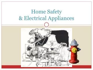
ELECTRICAL APPLIANCES. Our home is full of electrical appliances. They change electricity into a more useful form of energy. Some appliances use more energy than others – their POWER RATING is higher.

ELECTRICAL APPLIANCES
E N D
Presentation Transcript
ELECTRICAL APPLIANCES Our home is full of electrical appliances. They change electricity into a more useful form of energy. Some appliances use more energy than others – their POWER RATING is higher. Plugs are fitted with a fuse to protect the flex connected to the appliance. As a general rule a 3A fuse is fitted for appliances that use up to 700W and a 13A fuse is fitted for appliances that use more than 700W.
FUSES Fuses are used to limit the current flowing through a circuit or into an appliance. A fuse will melt when the current flowing through it exceeds the rating of the fuse. This protects the flex from overheating which could result in a fire. The circuit is then broken and the flow of current stops.
HUMAN CONDUCTIVITY The human body is a conductor of electricity. Water (moisture) increases the body’s ability to conduct.
EARTH WIRE The earth wire is a safety feature which prevents the metal casing of an appliance becoming dangerous to touch when a fault occurs. A large current will flow through the earth wire and the fuse will melt, protecting the appliance.
CIRCUIT BREAKER The circuit breaker is an absolutely essential device in the modern world, and one of the most important safety mechanisms in your home. Whenever electrical wiring in a building has too much current flowing through it, these simple machines cut the power until somebody can fix the problem.
DOUBLE INSULATION Double insulated appliances If you are fitting a plug to a double insulated appliance (labelled with the double insulated symbol), you should not have an earth conductor in your flex.
3 – PIN PLUG • Know colours and names of each wire. • Note how outer insulation is secured by cable grip.
ELECTRIC CHARGE A current of electricity is a steady flow of electrons. When electrons move from one place to another, round a circuit, they carry electrical energy from place to place like marching ants carrying leaves. Instead of carrying leaves, electrons carry a tiny amount of electric charge. Charge is calculated using: Q Q = It I t
MEASURING CURRENT 1 LEARNING To build a series circuit and measure the INTENTION current at different points in the circuit. APPARATUS: power supply, 2 lamps, connecting leads, switch and ammeter . . . C A B METHOD: Build circuit and measure current at points A, B and C
RESULTS: CONCLUSION: Current is the same at all points in a series circuit. IA = IB = IC
MEASURING VOLTAGE L. INT To build a series circuit and measure the voltage across L1, L2 and Vs. APPARATUS: power supply, 2 lamps, connecting leads, switch and voltmeter + Vs - L1 L2 METHOD: Build circuit and measure voltage across L1, L2 and Vs.
RESULTS: CONCLUSION: The supply voltage equals the sum of the voltages across the 2 lamps Vs = V1 + V2
CHANGING THE CURRENT L. INT.To investigate what happens to the current when components called resistors are placed in a circuit. APPARATUS:power supply, lamp, resistors with different values, connecting leads, switch and ammeter. Vs - + A METHOD:Build circuit using smallest resistor and measure corresponding current. Repeat for other resistors.
RESULTS: As the resistance increases the current decreases. CONCLUSION:
VOLTAGE, CURRENT & RESISTANCE L. INT.To find the relationship between voltage, current and resistance. APPARATUS:power supply, resistors, connecting leads, switch, ohmmeter, voltmeter and ammeter. Vs + - A Circuit 1 V Circuit 2 METHOD:Measure value of resistors using circuit 1. Put smallest resistor into circuit 2, measure current and voltage. Repeat for other resistors.
RESULTS: CONCLUSION: V = I x R
RESISTANCE OF A TORCH BULB L. INT. To investigate how the resistance of a torch bulb varies when the brightness changes APPARATUS: power supply, bulb, voltmeter, ammeter, connecting leads. METHOD: Build circuit Set supply at 2v Measure current & voltage Record in table & repeat for different voltages Vs + - A V
RESULTS: CONCLUSION:
RESISTANCE OF A THERMISTOR A thermistor is a temperature dependent resistor. L. INT. To find out how the thermistor varies with temperature APPARATUS: thermistor, ohmmeter, hot & cold water METHOD: (i) connect thermistor to ohmmeter (ii) place thermistor in cold water, record resistance (iii) place thermistor in hot water, record resistance RESULTS: CONCLUSION: As the temperature increases the resistance decreases.
RESISTANCE OF AN LDR An LDR is a light dependent resistor. L. INT. To find out how the LDR varies with light APPARATUS: LDR, ohmmeter, METHOD: (i) connect LDR to ohmmeter (ii) place LDR in the dark, record resistance (iii) place LDR in the light, record resistance RESULTS: CONCLUSION: As the light level increases the resistance decreases.
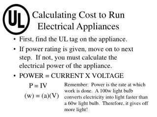
POWER, ENERGY & TIME To find the ENERGY used by an electrical appliance we need to know the POWER RATING of the appliance and the TIME the appliance is on. The energy can be found by multiplying the power by the time:- Where E = energy (J) P = power (W) T = time (s) E = P x T
POWER , CURRENT & VOLTAGE LEARNING To investigate the relationship between POWER, INTENTION CURRENT & VOLTAGE. APPARATUS: power supply, lamps ( different power ratings ), ammeter, voltmeter & connecting leads. Vs METHOD: Build circuit using 24W lamp. Switch on and record current and voltage. Repeat for 36W lamp. + - A V
RESULTS: CONCLUSION: By comparing the first and last column we have shown that the POWER equals the CURRENT multiplied by the VOLTAGE. P = I x V
MEASURING CURRENT 2 LEARNING To build a parallel circuit and measure the INTENTION current at different points in the circuit. APPARATUS:power supply, 2 bulbs, connecting leads, switch and ammeter . . +- . A B C METHOD:Build circuit and measure current at points A, B and C
RESULTS: CONCLUSION: the current at A equals the sum of the currents at B and C IA = IB + IC
MEASURING VOLTAGE 2 LEARNING To build a parallel circuit and measure the INTENTION voltage across bulbs 1 & 2 and Vs APPARATUS:power supply, 2 bulbs, connecting leads, switch and voltmeter. Vs METHOD:Build circuit and measure voltage across both lamps.
RESULTS: CONCLUSION: Supply voltage equals the voltage across bulb 1 which equals the voltage across bulb 2 Vs = V1 = V2
FAULT FINDING Two common electrical faults are ‘open circuits’ and ‘short circuits’. As every electrical component, from a lamp to a piece of wire, has a resistance, we can use this knowledge to identify such faults using an ohmmeter. OPEN CIRCUIT: the ohmmeter reads infinity as this is the result of a broken wire or a burnt out element. SHORT CIRCUIT: the ohmmeter reads a value that is less than expected for that component, as it’s the result of a touching wire.
RESISTANCE IN SERIES LESRNING To investigate how the individual resistors INTENTION compare with the total resistance in a series circuit APPARATUS: resistors, ohmmeter & connecting leads METHOD: measure each resistor individually connect them in series measure total resistance RESULTS CONCLUSION: RT = R1 + R2
RESISTANCE IN PARALLEL LEARNING To investigate how the individual resistors INTENTION compare with the total resistance in a parallel circuit APPARATUS: resistors, ohmmeter & connecting leads METHOD: measure each resistor individually connect them in parallel measure total resistance RESULTS CONCLUSION: 1/RT = 1/R1 + 1/R2
CONSUMER UNIT The consumer unit contains the fuses or circuit breakers that protect the mains wiring.
Kilowatt-hour Electricity companies charge their customers for each unit of electricity used. 1 unit of electricity is equal to 1Kilowatt-hour (1KWh), which is the amount of energy a 1KW appliance uses in 1 hour. It can be calculated using E = P x t. If power is in KW and time in hrs then E will equal the number of units used.
RING MAIN • The power sockets in a house are connected by means of a ring circuit. There are 2 paths to each socket which means half the current in 1 path and half in the other. The cables are thinner and therefore cheaper and less heat is produced in them.
ELECTROMAGNET An electromagnet is simply a coil of wire which is wrapped around a soft iron core. When the wire is connected to a power source a magnetic field is created and the iron core acts like a permanent magnet. The strength of an electromagnet can be increased by using more turns of wire or a larger current.
ELECTRIC MOTOR When a current flows along a wire which is in a magnetic field, the wire experiences a force, causing it to move (see crocodile physics). Rotation of motor can be changed by changing the direction of current or the direction of the magnetic field. Commutator reverses current; multi-segment commutators give smoother rotation; brushes allow current to flow into commutator.