Download
1 / 14
140 likes | 223 Views
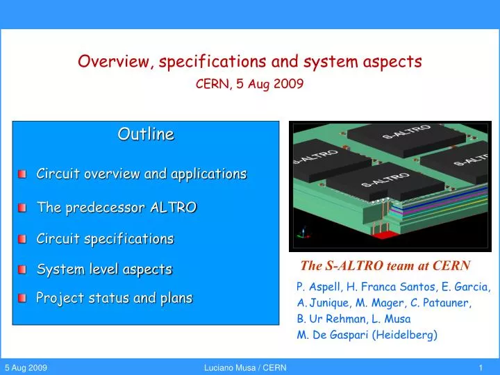
Overview, specifications and system aspects CERN, 5 Aug 2009. Outline Circuit overview and applications The predecessor ALTRO Circuit specifications System level aspects Project status and plans. The S-ALTRO team at CERN. P. Aspell, H. Franca Santos, E. Garcia,

E N D
Overview, specifications and system aspects CERN, 5 Aug 2009 Outline Circuit overview and applications The predecessor ALTRO Circuit specifications System level aspects Project status and plans The S-ALTRO team at CERN • P. Aspell, H. Franca Santos, E. Garcia, • Junique, M. Mager, C. Patauner, • Ur Rehman, L. Musa • M. De Gaspari (Heidelberg)
A multi-purpose readout chip for TPC detectors • SALTRO is a multi-purpose charge-amplifying, digitizing, processing and read-out chip • Designed for Time Projecting Chambers (TPCs) with MPGD or MWPC readout • In general suitable for applications that need sampling charge signals with 10-bit dynamics and up to 40 MHz frequency • It is a further development of the ALICE TPC chip set (PASA and ALTRO) • It consists of 64 complete signal acquisition lines (channels) • A single read-out channel is comprised of five basic functional parts • Charge Sensitive Amplifier & Shaping Amplifier (CSA & SHA); • 10-bit 40 MPS ADC; • baseline correction, signal conditioning and zero suppression • multiple-event acquisition memory (MEB) • lossless data compression
Main design parameters of the TPCs under study (*) Design parameters for an LCTPC with standard electronics. A new concept (CMOS Pixel readout) is under development
L1: 6.5ms 1 KHz L2: < 100 ms 200 Hz ALTRO (ALICE TPC Read Out) chain power consumption < 40 mW / channel DETECTOR Front End Card (128 CHANNELS) smallest pad 4 7.5 mm2 drift region 92ms Custom Backplane kapton cable 8 CHIPS (16 CH / CHIP) 8 CHIPS (16 CH / CHIP) ALTRO gating grid Digital Circuit PASA RCU ADC RAM anode wire CUSTOM IC (CMOS 0.35mm) pad plane 570132 PADS CUSTOM IC (CMOS 0.25mm ) (3200 CH / RCU) CSA SEMI-GAUSS. SHAPER • BASELINE CORR. • TAIL CANCELL. • ZERO SUPPR. 1 MIP = 4.8 fC S/N = 30 : 1 DYNAMIC = 30 MIP 10 BIT 10 MHz MULTI-EVENT MEMORY GAIN = 12 mV / fC FWHM = 190 ns PASA can only read unipolar positive going signals (like those produced by a MWPC with cathode pad readout)
PASA CHIP Power Regulation Board Controller (FPGA) 17 cm ALTRO CHIP 19 cm Alice TPC FEE – MWPC Readout 128-channel Front End Card Density 200mm2 / channel
A multi purpose readout chip for TPC detectors • Circuit Main Features • 64 complete readout channels (from detector pad to data link) • programmable charge sensitive amplifier • sensitivity to a charge in the range ~102 - ~106 • programmable shaping time in the range 30 to 300ns • 10-bit 40 MSPS ADCs • 8k multi acquisition memory per channel (dynamically allocated) • digital signal conditioning (4th order IIR filter and FIR filter) for baseline correction • 3-D zero suppression • lossless data compression • readout net work controller • output bandwidth 160 Mbyte/sec A multi-purpose readout chip for TPC detectors
Studies on readout plane layout (1/4) • Chip dimensions (die size in CMOS 130nm) • charge amplifier0.2 mm2 (prototype circuit) • ADC 0.7 mm2 (prototype ADC room for improvement) • data processor 0.6 mm2 (estimate) • In the following we shall assume • Readout module size: 27 × 27 cm2 (full surface available for components loading) • 4mm2 pads • 1.5mm2/channel (64 ch / chip ~ 100 mm2) • 16384 pads / readout module, 256 readout chips • readout chip package: bare die flip-chip mounted or CSP (chip scale package) • almost minimum-size (0.6x0.3x0.3mm3) capacitors • standard linear voltage regulators • data link based on ALICE SPD GOL MCM
Digital PWR planes Analogue PWR planes Studies on readout plane layout (2/4) PC board topology PC board layer stack-up 8-layer PCB digital signals II vdd gnd digital signals I gnd det gnd pad signal routing pad layer Flip-chip mounted Chip floorplan amplifiers ADCs PCB Digital Processing Digital Processing ADCs amplifiers
Studies on readout plane layout (3/4) Placing the components and routing pad signals to SALTRO inputs Definition of the layer stack-up decoupling capacitors Designing the power planes First attempt of implementing a cooling grid analogue plane digital plane
Studies on readout plane layout (4/4) Many essential aspects have to properly addressed (e.g. power delivery network) Many details have to be included (e.g. decoupling network for LDOs and optical components) First studies are very encouraging Under the assumptions made in slide 7, it seems feasible to instrument with the complete readout electronics a readout pad plane with pads as small as 4mm2 • These studies will continue • finalizing PC board design • electrical aspects • mechanical & thermal aspects • build a prototype module
Considerations on power dissipation • Power consumption • amplifier 8 mW / channel • ADC 12mW/channel (10MSPS), 34 mW / channel (40MSPS) • Digital Proc 2 mW / channel • data links 2 mW / channel • power regulation efficiency: 75% • Total power 32mW/channel (10MSPS), 60mW/channel (40MSPS) • Owing to the bunch-train time structure (beam duty cycle 0.5%), for the ILC and CLIC TPCs electronics a basic ingredient is power pulsing • In principle a factor ~70 (~1.5% electronics duty cycle) can be achieved • What can be achieved in practice is an important R&D issue • duty cycle 1.5% • average power / channel 0.5 mW / channel (at 10 MSPS) • average power / m2 100 W (at 10MSPS) • Power pulsing cannot be applied to PANDA
Considerations on power dissipation, cooling and material budget COOLING PLATES (COPPER) 7W / board WATER COOLING PIPE • ALICE TPC Electronics • PC board ~150mm Cu (0.1 X0) • 22mW / cm2 220W / m2 • 0.3mm copper plate (0.2 X0) • Using Al instead of Cu for cooling plate • kCU/kAl = 1.6, XAl / XCU = 6.2 • cooling plate = 5% X0
Comparison of published ADC power data B. Murman et al., “Power Dissipation Bounds for High-Speed Nyquist Analog-to-Digital-Converters” IEEE Transaction on Circuits and Systems – I: Regula Papers, VOL. 53, NO. 3, March 2009 Trend of decreasing power dissipation for flash and pipeline ADCs P/fS has halved every 2.5 years over the past ten years SALTRO ADC prototype design value ADC power data published between 1997 and 2007 at International Solid-State Circuit Conference (ISSCC) VLSI Symposium PS≡ minimum required Sampling Power
Status & Plans • Status • 2006 12-channel prototype of CSA (no programmability) • 2007 16-channel prototype programmable (1000 chips for LPTPC @ Desy) • 2009 2-channel ADC prototype (samples arrived in July) • 08/09 specifications digital blocks and design entry (Verilog) of data processor • 2009 first design of readout board • Plans • 2009 • characterization of ADC samples (Aug) • optimization of ADC design or ADC IP (S3) and migration to IBM 130nm • design of 16-channel of complete readout chain (with simplified digital processor) • 2010 • characterization of 16-channel prototype • decide how to continue the project according to the results achieved