Download
1 / 9
90 likes | 124 Views
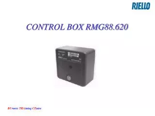
The RMO88.530 control box is dedicated to both light and heavy oil burners, offering precise control and safety features. This control box operates with one, two, or three-stage burners, ensuring efficient and reliable performance. The model includes various features like under-voltage protection, primary fuse protection, and power consumption monitoring. With detailed mode of operation and timings provided, it ensures the burner functions smoothly. The control program includes self-diagnostic capabilities for fault indication and easy troubleshooting, enhancing user experience and safety. The unit is designed for easy operation and maintenance, making it ideal for industrial settings requiring reliable burner control systems.

E N D
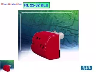
Dedicated to: Light oil burners PRESS SERIES ONE STAGE TWO STAGE THREE STAGE RL SERIES ONE STAGE TWO STAGE
Dedicated to: Heavy oil burners PRESS SERIES TWO STAGE THREE STAGE RN SERIES TWO STAGE
MODELS FEATURES RMO88.530A2RL RMO88.530A1RL Mode operation………….…... Intermittent Intermittent Main voltage…………….…... AC 220-240 V +10% -15% AC 100-120 V +10% -15% Frequency…………….…... 50-60 Hz +/-6% 50-60 Hz +/-6% Under Voltage protection…... Approx. AC 170 V Approx. AC 70 V Primary fuse…………….…... Max 16 A Max 16 A Power consumption……..…... 20 VA 20 VA Internal fuse…….……..…... T6.3H250V (IEC 127-215) T6.3 Polarity...………….……..…... To be observed To be observed >450 K (pre-purge) <200 K (operation) >450 K (pre-purge) <200 K (operation) Flame signal (photoresistence)
RMO88.530A2RL RMO88.530A1RL Timings of cycle NOTES Waiting time………….…... 2 sec………………………….. Beginning when both # 4 & # 8 are energised. If not input to # 4 within 600 sec since # 8 is energised lock out Pre-purge time (min)….…... 23 sec…………………………. Interval between # 11 # 10 outputs Pre-ignition time………….…... 22 sec………………………... Interval between # 12 # 10 outputs Post-ignition time……….…... 5 sec Ignition safety time……..…... 5 sec Interval 1st 2nd stage..…... 7 sec…………………………. Interval between # 10 # 13 outputs Interval 2st 3rd stage..…... 7 sec…………………………... Interval between # 13 # 14 outputs
SELF-DIAGNOSTIC Operating concept · Burner control has initiated lockout Þ Red fault LED on · Reset Press lockout reset button for about 1 s · Diagnosis of cause of fault – Press lockout reset button for > 3 s – Press again lockout reset button for > 3 s – Read blink code of red fault LED Þ «Error code table A»
Error code table A Blink code Possible cause 2 x ··· No establishment of flame at the end of ignition safety time – Faulty or soiled flame detector – Faulty or soiled fuel valves – Poor adjustment of burner – Faulty ingnion equipment 4 x ····· Extraneous light during pre-purging – Or internal device fault 7 x ········ Loss of flame during operation – Poor adjustment of burner – Faulty or soiled fuel valves – Faulty or soiled flame detector 8 x ········ · Time-out release contact for oil pre-heater does not close 10 x ·········· · Wiring error or internal fault, output contact, unidentifiable fault, e.g. faults that occurred simultaneously