Download
1 / 35
350 likes | 481 Views
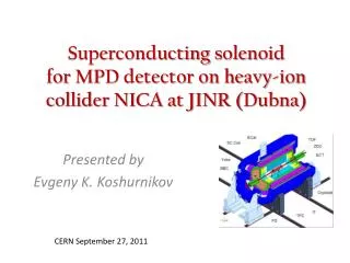
Superconducting solenoid for MPD detector on heavy-ion collider NICA at JINR ( Dubna ). Presented by Evgeny K. Koshurnikov . CERN September 27, 2011. Superconducting solenoid of Multi-Purpose Detector (MPD).

E N D
Superconducting solenoid for MPD detector on heavy-ion collider NICA at JINR (Dubna) Presented by Evgeny K. Koshurnikov CERN September 27, 2011
Superconducting solenoid of Multi-Purpose Detector (MPD) • The main component of the Multi-Purpose Detector (MPD) on heavy-ion collider NICA is a large 0.5 T superconducting solenoid. It has to provide resolution for transverse momenta over the range 0.1‑3 GeV/c. • The magnet is designed as a superconducting solenoid with a flux return iron yoke and with aluminium stabilized coil implying an inner winding method and circulating indirect cooling. • The magnet has to be commissioned in 2017.
General view of MPD The magnet inner dimensions are chosen as a compromise between the time of flight requirements to length of tracks to be sufficient for good particle identification and track reconstruction precision on one side, and the needs in homogeneous magnetic field and reasonable cost of the magnet on the other side.
Interface requirements The solenoid aperture volume is determined by arrangement of the inner detectors ΔZ=5.24m; Ø=4m • Requirementfor cryostat radiation transparency is not considered • It takes pole taper bores 14°- acceptance for two future forward spectrometers • Important requirement! The installed electrical capacity in Dubna is very limited. So the decision was taken for benefit of superconducting winding
Magnetic field requirements • Magnetic field requirements are optimized for momentum resolution of particles. • Requirement for integral of radial component of the magnetic field • Rated magnetic field in the aperture 0.5T • High level homogeneity dictates requirements for the magnet geometry stability under action of the magnetic forces and after magnet transportation to assembly area and back
MPDSolenoid Design Distinctive features of the magnet • high field homogeneity in the tracker area, • heavy weight and large dimensions of the system. Accepted conceptis the well proved design • Solenoid with a thin winding,pure aluminum stabilized NbTisuperconductor, indirect cooling of the coil, and flux return iron yoke • Yoke geometry stability is secured by the rigidity of two support rings joined by twelve flux return legs (this design is analogues to STAR magnet yoke design) • Two correcting coils with higher linear current density at the ends of the main coil and trim coils on the poletips Other magnet features • The magnet doesn’t have doors. The poles are being inserted in axial direction • Inner detectors are fixated on the yoke support rings. So the inner shell of the cryostat is not loaded by addition weight of the detectors
MAGNETIC FIELD CALCULATIONS OPERA-3D and FE-2D software, original FORTRAN and Mathcad – based computer codes FE TOSCA model (1.8 ∙ 106 ÷ 5 ∙ 106 nodes)
MAGNET OPTIMIZATION • The goal of optimization is minimization of the integral of the radial component of magnetic induction keeping minimal values of main and corrective coil current density difference and current density in the trim coil with help of Mathcad – based computer code • Optimization parameters are: • Relation of current densities of corrective and main sc coils JCORR / JSC, • Trim coil current density JTRIM • SC coil current density JSC. • Two first parameters are independentand the last parameter depends on the first two parameters trough the average magnetic induction in TPC area. SC corrective coil center position dependence for radial component integral in the TPC area and relation of sc coils current densities • |δ| < 0.12% Very high homogeneity of magnetic field and very low integral of radial component for the TPC area are achieved • Intmax=0.17 mm< 0.775 mm
SC solenoid coil Cooling tube length 80 m , diameter 18 mm • One layer coil is wound on the inside of the structural aluminum alloy Al5083 cylinder • Indirect cooling by force two-phase helium • Two corrective coils with the current density about 6% higher than in central coil • Radial conductor size and aluminium cylinder thickness provides acceptable temperature rise after a quench and keeping of the coil shape under gravity. Radial deformation of the coil loaded by gravity, magnetic pressure and radial decentering force <0.5mm • Maximal radial magnetic pressure 0.12 MPa, maximal axial compression force 470 kN.
Main parameters of the conductor Aluminiumstabilized conductor with central sc wire Ø1.2 mm • The critical parameters of the conductor for low inductions were chosen on the base of approximation expressions • L. Bottura. “A practical fit for the critical surface of NbTi”. CERN, LHC Project Report, MT-16, 1999. • The design current 1.59kA is ~40% along the load line to the conductor capability at the temperature 4.5 K. The maximal current corresponds to a temperature 7.2 K leaving a temperature margin of greater than 2.7 K at the maximal induction 0.61 T at the coil end. • MQE ~1 J/cm3
Influence of technological deviations on the magnet parameters *Cumulative effect of all axial deviations given in the previous lines of the table
6 axial ties Cryostat design Control Dewar Cryostat supports Stainless steel cryostat: to=16mm/ti=13mm. Maximal overpressure– 0.7 Bar. 2x12 radial ties
Cryogenic system Forced Two-Phase cooling system Helium circuit parameters • Heat load at T=4.5 K, W 46 • Heat load on the Control Dewar • heat exchanger, W 123 • Refrigerating capacity (including • thermal screen), W 220 • Forward flow, g/s 9.8 • Return flow, g/s 9.58 • The flow trough the current leads, g/s 0.22 • Steam-content in the inlet/outlet of • heat exchanger, % 5/ 23 • Pressure drop in the cooling tube, kPa4.7 • Gaseous Helium flow for thermal screen, g/s 2.9 Cryostatting cycle in T-S diagram «Linde» Refrigerator LR140, 210- 255W at 4.5K
Yoke Assembly at the factory and in the Experimental building Weights of the magnet main parts
Assembly/Operation conditions Rails for magnet and platform transportations Iron yoke and cryostat with assembled inner detectors Assembled magnet Platforms for equipment and electronics Parking Position Operation Position Accelerator ring Magnet poles on their rails
Moving and Supports Systems Yoke movement – 2 hydraulic cylinders Pole insertion – 2+2 cylinders Yoke supports – 6 cylinders Hilman Rollers • The magnet has: • Two hydraulic horizontal drive cylinders for translation of the detector, which have positional feedback gages of the pistons. • Controller which allows operation of each cylinder either independently or synchronously. • At every stage of movement the free ends of the cylinders are fixed on the floor. The detector is translated of 1.5m and after that the pistons repositioned in new positions on the floor for the next step of translation.
Solenoid Coil Quench Protection Protection Circuit Quench processes were modeled by means of Vector Fields Software QUENCH model of electric circuit QUENCH FE design model R1 = 1.3 ∙ 10-3 Ohm R2 = 0.3145 Ohm S1 opens when Vnz>1 Volt symmetry: 1/2 in axial and 1/32 in azimuthal direction
MODELLING OF THE COIL PROTECTION QUENCH, TEMPO and ELEKTRA modules of the OPERA-3D software Al cylinder Air Insulation SC coil Yoke pole Temperature distribution: 40 sec after quench starts Detail of FE QUENCH model (2.5 ∙ 106 nodes) Quench-back effect is seen (60 sec after quench starts)
RESULTS OF THE QUENCH TRANSIENT ANALYSIS Energy extraction to the external dump resistor Energy extraction without active protection
Yoke deflected mode under action of gravity and magnetic forces • Maximal pole to pole approach distance <2 х 0.5 mmfor rated solenoid current and • for ANY combination of the magnet support reactions The magnetic force applied to the pole = 960kN. Maximal vertical deflection of the support cradles when magnet is rested on two supports <1mm • Maximal stresses (membrane+bending) are located in the Yoke cradles Normal operative condition , MPa[169]43 Violation of Normal operative Conditions , MPa[234]56
Stress in the CryostatShells Vertical deformation of the cryostat shell Equivalent stress in the cryostat shell Operative magnet on two diagonal supports. Magnet transportation . Two diagonal supports
Conclusion • The most critical features of the magnet of Multi-Purpose Detector (MPD) : • low value of integral of radial component of magnetic induction • large overall dimensions and heavy weight • The solenoid design provides very rigid fixation of the yoke and cryostat parts. The mutual positions of the solenoid parts are secured against action of gravity and magnetic forces after multiple magnet transportations to beam/parking position and removing/insertion of the poles .
Deformation of the coil loaded by gravity, magnetic pressure and radial decentering force Coil space fixation by 2 x 12 radial ties Two 45 mm thickenings on both ends of the support cylinder The origin of decentering force: 20 mm vertical off-center coil displacement Radial displacements The maximal radial deviation of the coil shape doesn't exceed 0.5 mm
Maximal stresses (membrane+bending) Yoke beams Magnet transportation , MPa[169]5,5 Normal operative condition , MPa[169]3,6 Violation of Normal operative Conditions, MPa[234]7,5 Cryostat outer shell and flanges/ Cryostat supports Magnet transportation , MPa[169]30,6/64,1 Normal operative condition , MPa[169]9,7/24,4 Violation of Normal operative Conditions , MPa[234]36,3/97,5 Yoke Support Rings & Poles Normal operative condition , MPa[169]10,3 Violation of Normal operative Conditions , MPa[234]11,0 Yoke cradles Normal operative condition , MPa[169]43,4 Violation of Normal operative Conditions , MPa[234]55,5
Maximal axial deformation of the yoke under action of gravity and magnetic forces Uz1<0.36mm Maximal pole to pole approach distance <2 х 0.5 mmfor rated solenoid current and for ANY combination of the magnet support reactions
Yoke footprint vertical deflection Maximal vertical deflection of ANY combination of the support point lost <0.94mm
Stresses in the coil • Tensile stress in aluminium 5083 support cylinder under action of differential thermal contraction and magnetic pressure =26 MPa < al=92MPa • Local axial tensile stress conductor/insulation because of differential thermal contraction =6 MPa(Axial prestress = 10MPa/162 ton) • Local shear stress conductor/insulation because of differential thermal contraction τ=12 MPa • Equivalent stress in the aluminium matrix of the conductor =11 MPa (plastic deformation is considered)
Thermomechanical stresses in the coil on the conductor/insulation boundaries • Local axial tensile stress • max=16 MPa> ins=10MPa • Local radial tensile stress up to =13 MPa> ins=10MPa • Local shear stress • τmax=12 MPa > τ=7MPa
Yoke Deflected Mode FE Computations Six magnet support points. Operative regime - Normal Conditions The pressure in two diagonal hydraulic mountings is 20% higher than in all other mountings. Operative regime - Normal Conditions Two diagonal magnet supports. Operative regime – Violation of Normal Conditions Step-by-step load application in the process of FE computation: Gravity load. The poles are not mounted Gravity load. The poles are mounted Gravity load. The poles are mounted. Magnet is rested on two diagonal support points Gravity load. The poles are mounted. Magnet is rested on two diagonal support points. Magnetic forces. M24/M42/M48 (magnet is in the beam position) Normal operative conditions , MPa[708]388/571/533 Emergency conditions , MPa[1000]1200/580/1110 Two critical Studs M48 M48 studs 2 x 72 pcs. Initial M48 stud tightening force 295 kN • Action • M24 → M27 • At least 2x3 beam/ring radial contacts