Download
1 / 50
500 likes | 685 Views
www.lbstructures.co.uk/ metspan.htm. www.superiorconcreteco.com/ tiltwall.html. www.covers-timber-structures.l.../ glulam.htm. STEEL. CONCRETE. TIMBER. STRUCTURAL SYSTEM. CONSTRUCTION PROCESS. STRUCTURAL SYSTEM. STRUCTURAL SYSTEM. CONSTRUCTION PROCESS. CONSTRUCTION PROCESS.

E N D
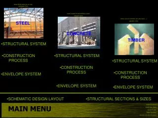
www.lbstructures.co.uk/metspan.htm www.superiorconcreteco.com/tiltwall.html www.covers-timber-structures.l.../glulam.htm STEEL CONCRETE TIMBER • STRUCTURAL SYSTEM • CONSTRUCTION PROCESS • STRUCTURAL SYSTEM • STRUCTURAL SYSTEM • CONSTRUCTION PROCESS • CONSTRUCTION PROCESS • ENVELOPE SYSTEM • ENVELOPE SYSTEM • ENVELOPE SYSTEM • SCHEMATIC DESIGN LAYOUT • STRUCTURAL SECTIONS & SIZES Adam Boskovic Nirbir Kaur Sibia Darryl Trotter Peter Scrimizzi Jennifer van den Bussche MAIN MENU
PREVIOUS MAIN MENU NEXT http://www.kleuven.ac.be/bwk/materials/Teaching/master/ Steel construction is used for the majority of single-storey buildings, due to the ability to design relatively light, long span, durable structures in steel which are easy to erect safely and quickly. The most common type of structure and in the projects case is the simple rectangular single-storey structure, which provides a weatherproof and environmentally comfortable space for carrying out manufacturing or for storage. www.steelstructureskenya.com/toc.htm www.unige.ch/cuepe/idea/_buildings/b_080/visi/page_03.htm http://www.kuleven.ac.be/bwk/materials/Teaching/master/wg14/l0200.htm Adam Boskovic Nirbir Kaur Sibia Darryl Trotter Peter Scrimizzi Jennifer van den Bussche STEEL STRUCTURAL SYSTEM
PREVIOUS MAIN MENU NEXT The optimum span of steel ranges from 15-40m. This is because of a high weight to span ratio. Steel portal frames can be heavy,this can be reduced by using lattice girder systems, which use much less steel, however the cost goes up due to manufacturing. Spans can be increased with additions of universal beam webs, providing pans up to 60m making it increasingly popular with industrial warehouse construction. Compared to other materials, particularly reinforced or prestressed concrete and timber, steel has major advantages. Steel has a high tensile and compressive strength, which enables steel buildings to be of relatively light construction. Steel is therefore the most suitable material for long-span roofs as they can also be modified easily for extension or change of use due to the ease with which steel sections can be connected to existing work. http://www.kleuven.ac.be/bwk/materials/Teaching/master/ http://www.kleuven.ac.be/bwk/materials/Teaching/master/ http://www.kuleven.ac.be/bwk/materials/Teaching/master/wg14/l0200.htm Adam Boskovic Nirbir Kaur Sibia Darryl Trotter Peter Scrimizzi Jennifer van den Bussche STEEL STRUCTURAL SYSTEM
PREVIOUS MAIN MENU NEXT The structure of a steel building, especially of an industrial building, is quickly erected and clad, providing a weatherproof envelope which enables the floor and installation of services and internal finishes to proceed at an early stage. Since the construction schedule is always tied to the earliest handover date fixed by production planning, time saved in construction is usually very valuable. In a dry closed environment steel does not rust, and protection against corrosion is needed only for the erection period. For other environments protection systems are available, which, depending on cost and suitable maintenance, prevent corrosion adequately. Diagram from Jeremy Ham Lecture power point http://www.kuleven.ac.be/bwk/materials/Teaching/master/wg14/l0200.htm Adam Boskovic Nirbir Kaur Sibia Darryl Trotter Peter Scrimizzi Jennifer van den Bussche STEEL STRUCTURAL SYSTEM
PREVIOUS MAIN MENU NEXT The two most popular arrangements of steel framing are the portal frame with pinned bases, if there is no crane to be supported, and the fully rigid portal frame, which is often used if there is a crane. These forms are both functional and economic. In- plane stability is derived from the provision of moment-resisting connections at the top and at the beam-to-column connections for the first situation and also at the base in the second one. Because of its economy, the most widely used building shape is the pin-based single or multi-bay pitched roof portal frame, typically of 20-40m span at 6m centres. Hot-rolled I, welded or cold-formed sections are usually used for the members. http://www.kleuven.ac.be/bwk/materials/Teaching/master/ http://www.kleuven.ac.be/bwk/materials/Teaching/master/ http://www.kleuven.ac.be/bwk/materials/Teaching/master/ http://www.kleuven.ac.be/bwk/materials/Teaching/master/ http://www.kuleven.ac.be/bwk/materials/Teaching/master/wg14/l0200.htm Adam Boskovic Nirbir Kaur Sibia Darryl Trotter Peter Scrimizzi Jennifer van den Bussche STEEL STRUCTURAL SYSTEM
PREVIOUS MAIN MENU NEXT When hot-rolled sections are used, haunches are usually provided at the eaves and the ridge. These haunches deepen the overall section, thereby reducing bolt forces. By extending the haunched regions along the rafter the frame is also strengthened and stiffened. http://www.kleuven.ac.be/bwk/materials/Teaching/master/ Diagram from Jeremy Ham Lecture power point http://www.kuleven.ac.be/bwk/materials/Teaching/master/wg14/l0200.htm Adam Boskovic Nirbir Kaur Sibia Darryl Trotter Peter Scrimizzi Jennifer van den Bussche STEEL STRUCTURAL SYSTEM
PREVIOUS MAIN MENU NEXT During recent years an increasing use of welded sections has occurred. This increase is the result of progress achieved in making welding automatic and the ability to adapt the cross-section to the internal forces.The ability to vary web thickness, flange dimensions and section depth results in high material efficiency. Deep slender sections are used to maximise economy. In addition to material economies there are benefits in reduced deflections resulting from the high in-plane stiffness of the deep sections. http://www.kuleven.ac.be/bwk/materials/Teaching/master/wg14/l0200.htm Adam Boskovic Nirbir Kaur Sibia Darryl Trotter Peter Scrimizzi Jennifer van den Bussche STEEL STRUCTURAL SYSTEM
PREVIOUS MAIN MENU END OF STEEL STRUCTURAL SYSTEM RETURN TO MAIN MENU The overall resistance of simple single-storey industrial buildings to horizontal loading is usually easy to achieve. One of the attractions of portal frame buildings is that in-plane stability follows from the rigidity of the frame connections. Bracing members for industrial buildings commonly use circular hollow sections, rods or angles. Bracing in one end bay may be sufficient. For longer buildings, bracing of two or more bays may be necessary. The rafter bracing itself provides restraint to the heads of the gable stanchions. The braced end bays provide anchor points to which the longitudinal rafter stabilising ties, which are usually the purlins, are attached. During erection, bracing facilitates plumbing and squaring of the building, as well as providing essential stability. http://www.kuleven.ac.be/bwk/materials/Teaching/master/wg14/l0200.htm Adam Boskovic Nirbir Kaur Sibia Darryl Trotter Peter Scrimizzi Jennifer van den Bussche STEEL STRUCTURAL SYSTEM
MAIN MENU NEXT Concrete panels can be used either as cladding to the building, or as part of the load bearing structure, supporting roof and wind loads, Cement &concrete assoc of Australia briefing 8-1-03 CONCRETE TILT UP STRUCTURAL SYSTEM Adam Boskovic Nirbir Kaur Sibia Darryl Trotter Peter Scrimizzi Jennifer van den Bussche Cement &concrete assoc of Australia briefing 8-1-03
PREVIOUS MAIN MENU NEXT The erection of the tilt up structural system incorporates the simplicity of the erection of the steel and timber portal frames. The concrete panels are lifted into position on the provided strip footings and temporarily braced. www.superiorconcreteco.com/tiltwall.html However it isn’t this process of the structural system that most attention is paid to but rather the joint detailing, incorporation of steelwork and bracing aspects of the system in order for it to function as an effective structural system. CONCRETE TILT UP STRUCTURAL SYSTEM Adam Boskovic Nirbir Kaur Sibia Darryl Trotter Peter Scrimizzi Jennifer van den Bussche Cement &concrete assoc of Australia briefing 8-1-03
PREVIOUS MAIN MENU NEXT When using concrete tilt up panels as a core structural material for warehouse construction, windows and other openings need to be considered when positioning joints within the concrete panels. Unlike a metal or timber based cladding material that is positioned on top of steel or timber portal frames with little regard for joints within these materials, concrete panels need to be of sufficient width and depth in order to contain sufficient strength as not to break around openings. Joints need to be kept to a minimum, however due to tilt up providing best results in large construction this is rarely achieved. CONCRETE TILT UP STRUCTURAL SYSTEM Adam Boskovic Nirbir Kaur Sibia Darryl Trotter Peter Scrimizzi Jennifer van den Bussche Cement &concrete assoc of Australia briefing 8-1-03
PREVIOUS MAIN MENU NEXT Joints at corners of the tilt up system need special attention and in majority of cases oversail joints are required, however this method may be unacceptable, as it requires showing a panel end on the façade. Oversail edge on structures front may be unattractive CONCRETE TILT UP STRUCTURAL SYSTEM Adam Boskovic Nirbir Kaur Sibia Darryl Trotter Peter Scrimizzi Jennifer van den Bussche Cement &concrete assoc of Australia briefing 8-1-03
PREVIOUS MAIN MENU NEXT To allow for a uniform wall appearance and treatment mitered joints are preferred, however these joints are susceptible to damage and impose greater restrictions on tolerances. A simple edge detail known as a chamfer is therefore required at the edges of panels reducing the chances of concrete being broken away from a panel. For joints to be a successful part of the structural system they need to be between 15-25mm, allow for slight movement between panels and be weather proof. A disadvantage of tilt up construction as opposed to steel of timber portal frame methods is that if attention isn’t paid to the minor details of the panels damage is inevitable. CONCRETE TILT UP STRUCTURAL SYSTEM Adam Boskovic Nirbir Kaur Sibia Darryl Trotter Peter Scrimizzi Jennifer van den Bussche Cement &concrete assoc of Australia briefing 8-1-03
PREVIOUS MAIN MENU NEXT A major advantage of the tilt up structural system is the incorporation of steelwork into the structural development. Steel rafters that are situated on the panels is known as racking, this method provides many advantages. Using panels as load-bearing elements generally reduces the overall cost of construction due to a decrease in the weight of structural steelwork required. Eliminating the columns that steel and timber portal frames contain usually provides greater savings. Also, in terms of the programming, the panels can be cast and erected prior to the delivery of steelwork, allowing time for fabrication of the steelwork. CONCRETE TILT UP STRUCTURAL SYSTEM Adam Boskovic Nirbir Kaur Sibia Darryl Trotter Peter Scrimizzi Jennifer van den Bussche Cement &concrete assoc of Australia briefing 8-1-03
PREVIOUS MAIN MENU NEXT Bay roof bracing Cement &concrete assoc of Australia briefing 8-1-03 Unfortunately the concrete tilt up system may be prone to progressive collapse, and redundancy needs to be incorporated into the structural system that provides stability and robustness. For instance, the failure of a single bracing member due to an event such as a fire, accident or abuse, should not lead to the collapse of the building. As a result of this more bracing members as opposed to steel and timber portal frames is needed. End walls act as shear walls to accommodate loads Cement &concrete assoc of Australia briefing 8-1-03 CONCRETE TILT UP STRUCTURAL SYSTEM Adam Boskovic Nirbir Kaur Sibia Darryl Trotter Peter Scrimizzi Jennifer van den Bussche Cement &concrete assoc of Australia briefing 8-1-03
PREVIOUS MAIN MENU END OF CONCRETE TILT UP STRUCTURAL SYSTEM RETURN TO MAIN MENU • If erection, joints, incorporation of steelwork and bracing is attended to in detail then the tilt up structural system provides many positive aspects in relation to other methods of framing such as steel and timber portal. • Economy. In areas where tilt-up design and construction expertise is available—particularly a trained crane and rigging crew—tilt-up has proven to be more economical than competing construction methods for similar types of buildings • Speed of Construction. From the time the floor slab is placed, the typical elapsed time from starting to form the panels until the building shell is completed is 4–5 weeks. • Fire Resistance. Concrete is an obvious first choice for fire resistance. A typical 150mm thick wall, for example, has a 90-120minute fire resistive rating. • Low Maintenance Costs. About the only thing needed is a coat of paint every 6–8 years. • Low Heating/Cooling Costs. The insulation value for tilt-up concrete often exceeds steel, masonry and wood frame construction. Tilt-up walls can be economically insulated to give higher insulation values. • Expandability. By planning for the possibility of expansion, panel connections can be designed so the panels can be detached and relocated. CONCRETE TILT UP STRUCTURAL SYSTEM Adam Boskovic Nirbir Kaur Sibia Darryl Trotter Peter Scrimizzi Jennifer van den Bussche Cement &concrete assoc of Australia briefing 8-1-03
MAIN MENU NEXT The use of timber as a material in warehouse construction provides the designers with a wide range of structural systems to employ. Whilst steel and concrete construction have been introduced and well accepted, timber has maintained its many advantages as a structural system including, aesthetic appeal, availability, workability and high strength to weight ratio. Also composite construction combining concrete/timber and steel/timber can prove to be effective design solutions. Cover of NAFI manual TIMBER STRUCTURAL SYSTEM Adam Boskovic Nirbir Kaur Sibia Darryl Trotter Peter Scrimizzi Jennifer van den Bussche NAFI manual
PREVIOUS MAIN MENU NEXT Although steel and concrete are relatively new forms of construction adapting a lot of the industries advanced technology, timber so to has implemented new technologies as well as products such as plywood, laminated veneer lumber and glued laminated timber that has significantly broadened the versatility of the timber structural system. www.covers-timber-structures.l.../glulam.htm Plywood sections NAFI manual TIMBER STRUCTURAL SYSTEM Adam Boskovic Nirbir Kaur Sibia Darryl Trotter Peter Scrimizzi Jennifer van den Bussche NAFI manual
PREVIOUS MAIN MENU NEXT Definitely the simplest form of timber construction mimics that of a steel portal frame. A timber post and beam portal frame is made up of beams and post, where roof loads are traditionally transferred down post and into appropriate footings. Much like a steel portal, roofing materials are supported by purlins spanning between beams and conventional girts support wall claddings. NAFI manual TIMBER STRUCTURAL SYSTEM Adam Boskovic Nirbir Kaur Sibia Darryl Trotter Peter Scrimizzi Jennifer van den Bussche NAFI manual
PREVIOUS MAIN MENU NEXT The most practical and cost competitive timber portal system for rectangular or square warehouse design is portals with nailed gusset plate joints at knees and apex. Straight or tapered sections are used for the columns and rafters with the advantages of ready availability, ease of transport and simple and economical erection. The latter advantage is experienced due to the large amount of experienced timber tradesmen. Unlike steel and concrete structural systems where only a minority of skilled labour exists, timber labour is easily found. NAFI manual TIMBER STRUCTURAL SYSTEM Adam Boskovic Nirbir Kaur Sibia Darryl Trotter Peter Scrimizzi Jennifer van den Bussche NAFI manual
PREVIOUS MAIN MENU NEXT The timber portal frame system is disadvantages in a sense, compared to steel as timber has lower modules of elasticity therefore deflections are more significant. If these deflections are not considered then permanent damage to the structural system and overall structure will occur. Typical frame bending moment diagram Pooling water Damaged cladding TIMBER STRUCTURAL SYSTEM Adam Boskovic Nirbir Kaur Sibia Darryl Trotter Peter Scrimizzi Jennifer van den Bussche NAFI manual
PREVIOUS MAIN MENU NEXT Timber portal frames as a structural system challenge both steel and concrete construction with regards to cost, spanning potential, workmanship and ease of fabrication. However there are a number of other advantages of this structural system. · Timber buildings can be adaptable in regards to their changes in use. Timber contains several of attributes that allow it to adapt with little or no risk for example a change in use from a storage warehouse to a chemical storage warehouse. Concrete and steel are susceptible to chemical attack where as timber is resistant to chemical attack. · Unlike other forms of construction, in particular the tilt up system, timber portals are able to tolerate relatively large movements such as one experienced due to reactive soils. While other structural systems may deform and break, timber will generally cope. · When the timber portal structural system is clad or attached to it is a multi story office building these assist greatly in providing high strength and rigidity in transferring lateral loads. · Although steel and concrete are available in standardized form and are suitable for many structures, the various properties amongst different timber species enables the selection of specific species that will suit the needs of a specific structural system. TIMBER STRUCTURAL SYSTEM Adam Boskovic Nirbir Kaur Sibia Darryl Trotter Peter Scrimizzi Jennifer van den Bussche NAFI manual
MAIN MENU END OF TIMBER STRUCTURAL SYSTEM RETURN TO MAIN MENU Through critical analysis of a number of structural systems that are appropriate for warehouse construction,the method that our group believes will effectively succeed in the construction of the warehouse project is a standard rigid portal frame, clad with architectural foam core panels developed by borrel in conjunction with BHP. The report outlines the positive aspects of such a structural system. the shared party wall between the office and warehouse will be concrete tilt up panel as this provides adequate sound and thermal insulation as well as a sufficient fire barrier between the two sections. TIMBER STRUCTURAL SYSTEM Adam Boskovic Nirbir Kaur Sibia Darryl Trotter Peter Scrimizzi Jennifer van den Bussche
MAIN MENU NEXT Two major types of wide span construction are COLUMN AND BEAM or CONCRETE PANELSThere are many different styles of column and beam construction which has evolved over the years. We based our research on the most popular of the column and beam, the Portal Frame. With links to: Structure Process chart With links to: Structure Process Chart Adam Boskovic Nirbir Kaur Sibia Darryl Trotter Peter Scrimizzi Jennifer van den Bussche Structural Systems
PREVIOUS MAIN MENU NEXT STEEL COMPARED TO TIMBERWe found it difficult to locate factories constructed from timber portal frames. In a country such as Australia with plenty of natural and renewable resources, this seems a silly situation. Perhaps due to the extra depth of members which eat into valuable internal space, although this does not affect so much because of the placement of timber purlins. Maybe because steel can span further at a lower pitch due to the elasticity of timber. Maybe it is good marketing on behalf of the steel companies. Perhaps laminating and finger jointing methods are a relatively new industry. The main difference between timber and steel structural system is the joint connection and the purlin connection. Steel purlins sit on top of the rood and timber purlins sit in between. Although there are no limit to the alternatives. Top chord supported timber truss purlins between steel UB rafters. Timber truss girts external of column supported by cleats Adam Boskovic Nirbir Kaur Sibia Darryl Trotter Peter Scrimizzi Jennifer van den Bussche Structural Systems
PREVIOUS MAIN MENU NEXT FOOTINGS Portal Frame construction can be a very flexible process in that the development can take a number of sequences depending on a number of factors, including site restrictions, time and economic viability. The following pages will explore a few examples. Footings are the main load bearing points of the building transferring main loads directly to the foundations below. Site excavation and footings are always dug and poured first. Pad footings are usually used for point loads such as column bases. Strip footings can be used in conjunction with pad footings for applications such as masonry veneer. Adam Boskovic Nirbir Kaur Sibia Darryl Trotter Peter Scrimizzi Jennifer van den Bussche Process - Portal Frame
PREVIOUS MAIN MENU NEXT BOLTED JOINTS Steel or timber members are usually delivered to site prefabricated and ready to be assembled into the final product in a variety of orders. Members are usually bolted together using the prefabricated plates and corresponding holes. They can be welded but this process cost time and requires added equipment and skilled labour. Adam Boskovic Nirbir Kaur Sibia Darryl Trotter Peter Scrimizzi Jennifer van den Bussche Process - Portal Frame
PREVIOUS MAIN MENU NEXT PORTAL ASSEMBLY ALTERNATIVE 1. Slabs poured first can be beneficial for a working surface such as assembling rafters or as in the instance below, carrying out alterations after the building works have begun. Care must be taken to not damage the concrete with loads heavier than the slab is designed for. Columns are raised singularly and bolted to tie downs in footings. On smaller jobs, this process can be performed safely by two man teams Bracing Tie Down Rods Adam Boskovic Nirbir Kaur Sibia Darryl Trotter Peter Scrimizzi Jennifer van den Bussche Process - Portal Frame
PREVIOUS MAIN MENU NEXT PORTAL ASSEMBLY ALTERNATE 1. Rafters are then raised as one unit Rafters are bolted at the apex, lifted into place as one rafter and attached to the columns. This particular roof had been bolted and erected but had been taken down and had webs welded on to create a truss to support the roof of the factory in the background. These were late alteration to the original design which were permitted due to the bolted construction. ALTERNATIVE 1. SUMMARYCrane hire would increase in time but reduce in necessary size capacity.Labour would also increase in time but be reduced in intensityOverall site time seems to take the longest in this process. Portals can also be raised as one unit with both columns and rafters pre-assembled. Adam Boskovic Nirbir Kaur Sibia Darryl Trotter Peter Scrimizzi Jennifer van den Bussche Process - Portal Frame
PREVIOUS MAIN MENU NEXT PORTAL ASSEMBLY ALTERNATE 2. The entire roof can be assembled as one unit with beams and purlins and raised in blocks to be attached to the already standing columns. If safety mesh and sarking was also installed prior to roof lift, this would save on the labour and safety costs of installation at a much greater height. ALTERNATIVE 2. SUMMARY Crane hire would increased dramatically for the duration of the roof lift, but be for a much shorter duration. It would also require plenty of room on site. Cover of NAFI manual Adam Boskovic Nirbir Kaur Sibia Darryl Trotter Peter Scrimizzi Jennifer van den Bussche Process - Portal Frame
PREVIOUS MAIN MENU NEXT PORTAL ASSEMBLY ALTERNATE 3. Another system which has been recently developed but not used much in our local area, is the portal frame with a pin knee joint which is connected to the column, the rafters rigidly bolted together and the frame raised as one.This process works with both timber and steel portal frames. The portals can be lifted as a single unit, or the whole roof can be assembled and blocks of entire structural portal raised in one fluid motion. One problem encountered with this system is that as the columns are dragged along the ground to a vertical position, hold down bolts can be bent out of shape and slabs can be damaged. ALTERNATIVE 3. SUMMARY Special engineering would be required to calculate the extra force placed on the columns and pin knee joint. This added cost may be outweighed by the erection speed, especially if the roof cladding is installed prior to lift. . Diagram from Jeremy Ham Lecture power point Adam Boskovic Nirbir Kaur Sibia Darryl Trotter Peter Scrimizzi Jennifer van den Bussche Process - Portal Frame
END OF PORTAL FRAME CONSTRUCTION PROCESS RETURN TO MAIN MENU PREVIOUS MAIN MENU PORTAL ASSEMBLY ALTERNATE 4. The slab pouring process can be poured first, middle or last, depending on design and conditions Whether the veneer is iron, masonry or concrete, the slab can go last if the columns are not resting directly on top. This creates a solid seal between cladding and slab for weather and rodent proofing. If the roof cladding is installed early, then the slab is protected from weather and can be poured at any time, thus saving any possible weather delays. Adam Boskovic Nirbir Kaur Sibia Darryl Trotter Peter Scrimizzi Jennifer van den Bussche Process - Portal Frame
MAIN MENU NEXT CONCRETE TILT UP BASIC ELEMENTS This process consists basically of footings (pad or strip), a slab, and tilt panels manufactured either off or on site, raised in place with a crane to form the walls. This usually requires good site access and height clearance. The panels can be load bearing to support the roof or upper floors, or non-load bearing and used for aesthetics or on lower panels for safety and security reasons. Load Bearing Panels with beam attached directly to concrete panel via cleat cast or bolted into panel with ferrules (pictured above) Non-load bearing panel fastened to portal frame via ferrules Adam Boskovic Nirbir Kaur Sibia Darryl Trotter Peter Scrimizzi Jennifer van den Bussche Process Concrete Tilt Up
PREVIOUS MAIN MENU NEXT PRE FABRICATED VERSUS ON SITE FABRICATION Panels poured on site is a slower construction process as panels need curing time in between pours to gain strength for lifting which puts huge stresses on lifting points and ties up valuable site working space. It also requires good weather which is not always guaranteed in our climate. They can be poured separately over the whole slab (the slab must have good quality finish), or they can be stack cast. Due to the heavy loads, they may require a thickening of the slab, or even a temporary separate slab. Bond breakers (required to stop panels sticking to slab) may also have an effect on later applied finishes such as paint. There are also no transport restrictions so size limitations are limited to structure. www.innovation.org.au/transtilt.html If the construction time required is short, then prefabricated is the better option.However, site access would have to be fairly good to allow for placement of panels in a position close enough to panel lifting point. Quality is usually more controlled in a factory environment with greater accuracy. This is more expensive material wise but much less labour intensive. Lifting Lug Adam Boskovic Nirbir Kaur Sibia Darryl Trotter Peter Scrimizzi Jennifer van den Bussche Process Concrete Tilt Up
PREVIOUS MAIN MENU NEXT PROCESS ADVANTAGES Whilst waiting for later applied structural elements to stabilise the building, temporary props are used on either side of the panel. PROCESS DISADVANTAGES Tilt panels do not require outside access so they can be placed almost hard up against an existing building. This is also viable because of it’s high fire rating quality Panel edges are usually chamfered to prevent damage such as this occurring. However concrete is brittle and will be damaged if care is not taken. Adam Boskovic Nirbir Kaur Sibia Darryl Trotter Peter Scrimizzi Jennifer van den Bussche Process Concrete Tilt Up
PREVIOUS MAIN MENU NEXT PROCESS ALTERNATIVES Similar to Portal Frames, this process can be altered allowing much flexibility in process. The panels can be placed on top of the footings and the slab poured up to the wall allowing flexibility on a sloped site and creating a nice finish inside. Panels placed on top of strip footings first which allows the slab to be poured last. This creates a nice solid finish. In this case, the footings were poured, then the slab and then the wall panels were erected. The panels had no influence on the slab via connection. Adam Boskovic Nirbir Kaur Sibia Darryl Trotter Peter Scrimizzi Jennifer van den Bussche Process Concrete Tilt Up
END OF CONCRETE TILT UP CONSTRUCTION PROCESS RETURN TO MAIN MENU PREVIOUS MAIN MENU PROCESS ALTERNATIVES This is a panel with footings only at the support points. This is allowing for late addition of services which reduces possibility of damage by plant. Notice the FFL is above the level of holes which allow for grouting after the Y bars are in place. Adam Boskovic Nirbir Kaur Sibia Darryl Trotter Peter Scrimizzi Jennifer van den Bussche Process Concrete Tilt Up
MAIN MENU Click to view plans in further detail Adam Boskovic Nirbir Kaur Sibia Darryl Trotter Peter Scrimizzi Jennifer van den Bussche PLANS
MAIN MENU NEXT TILT UP CONCRETE PANELS Tilt up panels are being use quite a lot in resent years for outer wall cladding on factory walls and office spaces the concrete is a reliable and durable construction material it can be poured on site or off and transported to the site the extra cost of pre-cast is the time saving the decision to pour on site or off as both have for and against points this will be determined by the restrains of the contract and the working environment i.e. sloping site area over head wires. The size of the site may also determine the height of the panels needed. When erecting on a boundary the erecting process needs to be carefully analysed and consideration for water proofing, jointing, flashing. Crane size should also be considered. Advantages the panels can be made to order for flexible applications can eliminate columns but extra roof bracing is required, a variety of finishes can be added and it has a good Fire ratting. Disadvantages are that once it is erected it is hard to change chipping can occur on the edges and extra cost for experienced labour. A more complex planing of execution and delivery for precast and large spaces needed for on site pouring and time needed for curing a minimum of 28 days. And measurements need to be exact. Adam Boskovic Nirbir Kaur Sibia Darryl Trotter Peter Scrimizzi Jennifer van den Bussche ENVELOPE SYSTEMS
MAIN MENU NEXT PREVIOUS WALLING AND ROOFING Foam core cladding panels : foam core cladding panel are a light weight composite building material the is made up of two colour bond sheets which are pre-painted and are glued to an inner foam core. The foam can be of made from polystyrene or polyurethane depending on the application of the product or the proposed design. The panels range in thickness of 50mm p to 200mm and are pliable enough to be moulded or cranked to most architectural forms. 1. The structural steel base 2. Zinc/aluminium alloy coating 3. A conversion layer chemically applied to enhance coating adhesion 4. A corrosion inhibitive primer is baked onto the surface 5. A durable, exterior grade top-coat is baked on. The distinct advantage with the foam core is it insulating properties it resistance to weathering and the large rang of aesthetic colours, the disadvantage is the specialized fixing required and the cost and it is more suited to areas that need climate controlled spaces. Must be layed on a pitch greater than 5º FireClad® and Firestop® are registered to Boral Australian Gypsum Limited. Adam Boskovic Nirbir Kaur Sibia Darryl Trotter Peter Scrimizzi Jennifer van den Bussche ENVELOPE SYSTEMS
MAIN MENU NEXT PREVIOUS FIRE CLAD Fireclad® Exterior Wall System is a fire rated commercial walling system developed by Boral and refined in association with BlueScope Steel that adheres to the fire rating codes. The manufacturers clam that it can save up to 25% on wall thickness comparing with tilt up construction for the same fire rating. As it is attached to girts and purlins in a similar fashion to that of traditional sheet cladding it is quick and easy to install. The system, which complies with the Building Code of Australia, provides external fire resistance of either 60, 90 or 120 minutes. Easy to install where proximity to adjoining buildings prevents conventional construction Lightweight - less load on foundations and easy to handle Ideal for refurbishments and building upgrades Cost savings - In situations where half the external wall area of a building requires a fire rating, an independent cost analysis by Rider Hunt quantity surveyors indicates savings of 25% can be made on core building elements when FireClad® is used compared with conventional tilt-up construction www.lysaght.com Adam Boskovic Nirbir Kaur Sibia Darryl Trotter Peter Scrimizzi Jennifer van den Bussche ENVELOPE SYSTEMS
MAIN MENU NEXT PREVIOUS LYSAGHT CUSTOM ORB This is a corrugated profiled sheet of colour bond sheeting suitable for both wall and roof clawing with design aspects for lite traffic. Advantages: easy to align, lite, durable, quick and easy to install. It comes in a large range of colours if damaged easy to replace and extend. It has a relatively large spaning capacity in relation to supports. Can be made to length of up 24m. Disadvantages: Hard to install in high wind low insulation properties, can corrode if in contact with dissimilar metals, short life span in relation to other materials. www.stratco.com.au Adam Boskovic Nirbir Kaur Sibia Darryl Trotter Peter Scrimizzi Jennifer van den Bussche ENVELOPE SYSTEMS
MAIN MENU NEXT PREVIOUS D3-COMTEX This is a James Hardie, facade product it is constructed with 9mm fibre cement. With new innovation in these products the edges have rebates on each side to allow for seamless jointing. This product comes with a 5 year warranty. Advantages: aesthetic finish, easy installation. Comes in large sheets of 3×6m sheet TOP-DEK Top-dek is a Stratco roofing product it has a 50mm profile and come in width of 700mm sheet are rolled to length. Anything over 10m. will require special transport and min made lengths are 1.2m must be layed at pitch greater than 1º. Made from high tensile 550 MPa steel. Advantages: easy to handle for installation, the clipping system eliminates the need for washers and thus reduces the chance of rain penetration. Cold rolled for extra strength Disadvantages: not suitable for steep pitches and is not able to be cranked. www.infolink.com Adam Boskovic Nirbir Kaur Sibia Darryl Trotter Peter Scrimizzi Jennifer van den Bussche ENVELOPE SYSTEMS
MAIN MENU NEXT PREVIOUS ALSYNITE ULTRA FIBRE GLASS Made by Laserlite Australia Ltd. is a translucent roof sheeting for industrial application it come in a wide range of colours clear and opal. It is available with fire and corrosion resistant retardants. profiles – 1800gsm/m2 to 4880gsm/m2. Lengths as required www.infolink.com.au Adam Boskovic Nirbir Kaur Sibia Darryl Trotter Peter Scrimizzi Jennifer van den Bussche ENVELOPE SYSTEMS
MAIN MENU NEXT PREVIOUS PURLINS AND GIRTS Lysaght SupaZed and Lasagyht SupaCee purlins are another Bluescope product there clam is that they out preform any other purlin on the market per weight of steel. The clam comes from the design with a ribbed web and curve lip in the c and z sections this gives extra strength there fore longer spaning capacities www.lysaght.com Adam Boskovic Nirbir Kaur Sibia Darryl Trotter Peter Scrimizzi Jennifer van den Bussche ENVELOPE SYSTEMS
MAIN MENU NEXT PREVIOUS PERMAGAL PURLIN Permagal purlins have been producing heavy duty purlins since 1997, they are designed to fill the void in areas subject to corrosion i.e swimming pools, as they are hot dipped galvanised section Permagal Purlins are available in standard web heights from 100mm to 300mm.They are also available in 1.9mm, 2.4mm and 3.0mm steel thickness. Special arrangements can be made where thicker or non-standard thickness is require. Available in z and c sections. www.infolink.com Adam Boskovic Nirbir Kaur Sibia Darryl Trotter Peter Scrimizzi Jennifer van den Bussche ENVELOPE SYSTEMS
MAIN MENU NEXT PREVIOUS ROOF MESH Waratah Roof safe safety, it is designed to cover the entire roof once the purlins have been placed. The product specific purpose is to stop people from falling through when installing the roof . Waratah roofing mesh conforms to all required standards and comes in two sizes. www.infolink.com Adam Boskovic Nirbir Kaur Sibia Darryl Trotter Peter Scrimizzi Jennifer van den Bussche ENVELOPE SYSTEMS
MAIN MENU NEXT PREVIOUS WINDOWS Lidco: 50mm Perimeter framed / non ventilating Windows The window system is designed for low medium commercial buildings there are able to be link vertically and horizontally to provide a continuos run of windows. The aluminium sash is designed to cater for glazing from 4mm to 10mm, there is also a double glazing option,with a 25mm gap with a further option of an internal vertical blind system. www.lidco.com.au Adam Boskovic Nirbir Kaur Sibia Darryl Trotter Peter Scrimizzi Jennifer van den Bussche ENVELOPE SYSTEMS
MAIN MENU NEXT PREVIOUS INSULATION PermaStop Is made Insulation solutions it is designed for industrial and residential application for insulation of sheet roofing and sheet walling, it also acts as a water barrier. It comes in a range of sizes and thickness from R 1.5 to R2.5 Also a very affective moisture barrier. www.infolink.com Adam Boskovic Nirbir Kaur Sibia Darryl Trotter Peter Scrimizzi Jennifer van den Bussche ENVELOPE SYSTEMS
MAIN MENU PREVIOUS • BCA • NAFI MANUALS • TIMBER MERCHANTS ASSOCIATION • BHP BLUESCOPE • JEREMY HAM LECTURE NOTES • http://www.kuleven.ac.be/bwk/materials/Teaching/master/wg14/l0200.htm (STEEL RELATED WEBSITE) Adam Boskovic Nirbir Kaur Sibia Darryl Trotter Peter Scrimizzi Jennifer van den Bussche REFERENCES