Download
1 / 29
290 likes | 432 Views
A Design Approach for Radiation-hard Digital Electronics. Rajesh Garg Nikhil Jayakumar Sunil P Khatri Gwan Choi Department of Electrical and Computer Engineering, Texas A&M University, College Station, TX-77840. Outline. Introduction Objective Previous Approaches Our Approach Results

E N D
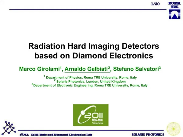
A Design Approach for Radiation-hard Digital Electronics Rajesh Garg Nikhil Jayakumar Sunil P Khatri Gwan Choi Department of Electrical and Computer Engineering, Texas A&M University, College Station, TX-77840
Outline • Introduction • Objective • Previous Approaches • Our Approach • Results • Conclusions
Introduction • There has been significant interest in the radiation immunity of electronic circuits • Historically mainly used for space and military electronics • Higher levels of radiation in space and combat environments • More recently, terrestrial electronics are also becoming vulnerable • Shrinking feature size and supply voltages • Reduced capacitances means less charge is required to flip node voltage • This has led to a renewed interest in radiation tolerant circuit design
Introduction (contd.) • Effects of radiation particle strike • Neutron, proton and heavy cosmic ions • Ions strike diffusion regions • Deposit charge • Results in a voltage spike • What is Single Event Upset (SEU)? • Interaction of a radiation particle with VLSI circuits can produce a charge deposition in critical regions of the circuit, leading to a bit reversal error, or single event upset.
Introduction (contd.) • Charge deposited (Q) at a node is given by where:Lis Linear Energy Transfer (MeV/cm2/mg) tis the depth of the collection volume (mm) • Resulting current pulse is modeled as where:tais the collection time constant tbis the ion track establishment constant
Objectives • Radiation particles cause SEU • Terrestrial electronics are also susceptible to SEU • Therefore, need circuit level protection against SEU even for consumer electronics • To make circuit radiation tolerant • Delay and area overhead should be minimized
Previous Approaches • Transistor sizing is done to improve the radiation tolerance of the design (Zhou et. al) • Ensure that capacitance of any node is sufficient to make the circuit radiation tolerant. • SEU event is detected using built in current sensor (BICS) (Gill et. al) • Triple modulo redundancy based approach (Neumann et. al) • Error correction codes (Gambles et. al) • More detailed references can be found in the paper
Our Radiation Hardening Approach • Part 1: Gate Level SEU protection • Approach A: PN Junction Diode based SEU Clamping Circuits • Approach B: Diode-connected Device based SEU Clamping Circuits • Part 2: Logic Block Level Protection • Radiation hardening for all gates • Fixed depth protection • Variable depth protection
Our Radiation Hardening Approach • Approach A - PN Junction Diode based SEU Clamping Circuits V (out) Radiation Strike 0.8 1V 0.6 0.4 in out 0.2 G 0 time 0V D2 D1 1.4V V (outP) 0.8 outP GP 0.6 0.4 Shadow Gate -0.4V 0.2 Higher VT device 0 time -0.4
Our Radiation Hardening Approach • Approach B - Diode-connected Device based SEU Clamping Circuits V (out) Radiation Strike 0.8 1V 0.6 0.4 in out 0.2 G 0 time 0V D2 D1 Ids 1.4V V (outP) 0.8 outP GP 0.6 0.4 -0.4V 0.2 Higher VT device 0 time -0.4
Our Radiation Hardening Approach • Compared approaches A and B • Performed layout and spice level simulation • Approach A has higher area penalty than B • But performance of approach A is slightly better than B • Therefore, selected approach B
Simulating a Radiation Strike • Circuit simulation is performed in SPICE • 65nm BPTM model card is used • VDD = 1V • VTN= | VTP| = 0.22V • The radiation strike was modeled as current source • As commonly done in this field (Zhou et. al) • Varied the value ofQandta • tbis chosen to be 5ps (Gill et. al)
Simulating a Radiation Strike • Injected Current as a function ofQandta
Protection Performance - Example • Radiation strike at output node. • Q = 4 fC • ta= 10ps • Approach B is used
Block Level Radiation Hardening • Individual gate protection • Approach B is selected • Area overhead is more than 100% • But our goal is to protect the entire logic circuit • We call it as block level protection • To understand block level protection • Critical depth of a gate
Critical Depth of a Gate • Consider 2 input AND gate • Computed for each hardened cell Produces glitch Magnitude of glitch reduces Radiation Strike Glitch magnitude is tolerable 1 1 1 1 1 Critical Depth =3
Critical Depth of a Gate • Spice simulations were performed using Q = 5 fC, ta= 10ps, tb= 5ps • Tolerable glitch magnitude is 0.35*VDD
Block Level Radiation Hardening • Simple approach – radiation hardening for all gates • Very inefficient approach • Large delay and area overhead Primary Outputs Primary Inputs
Block Level Radiation Hardening • Better approach – Fixed depth protection • Let Δmax= maxC(Δ(C)) • Assume Δmax = 2 then Radiation Strike Radiation Strike Primary Outputs Primary Inputs
Block Level Radiation Hardening • Further improvement – Variable depth protection Primary Outputs Primary Inputs
Variable Depth Protection • LetΔ(INV2AA) = 4, Δ(NAND2AA) = 1 andΔ(AND2AA) = 2 • Maximum depth of protection required is 4 • More details of the algorithm can be found in the paper 3 8 6 1 Primary Inputs Primary Outputs 9 4 7 10 2 5
Experiments • Used our approach on some benchmark circuits. • Used SIS for synthesis and technology mapping. • Circuits were mapped for both delay and area. • Used the “sense” package in SIS to find circuit delays. • sense reports the largest sensitizeable delay. • To get accurate area estimates, circuits were placed and routed using SEDSM from Cadence. • QPLACE for placement, WROUTE for routing
Block Level Delay Results • Delay overhead primarily due to increased capacitive load from hardended cells.
Block Level Area Results • Area overhead is larger for circuits mapped for minimum area • Area overhead is also large for circuits with smaller logic depth (such as frg2)
Conclusions, Future Work • We have presented a novel circuit design approach for radiation hardened circuit design. • We use shadow gates and protecting diode-connected devices to protect the primary gate from a radiation strike. • We presented techniques to replace fewer gates to help minimize the area and delay penalties. • Only 30% area penalty and 4% delay penalty on average for circuits mapped for minimum delay. • In the future we hope to be able to incorporate radiation hardening in the technology mapping step itself.
Our Radiation Hardening Approach • Radiation strike at the output of the shadow gate • Output is protected upto 0.4+0.6+0.35 V glitch Radiation Strike V (out) 1V 0.8 0.6 in out G 0.4 0.2 0V 0 D2 D1 time 1.4V V (outP) 0.8 outP GP 0.6 0.4 Shadow Gate -0.4V 0.2 0 time -0.4
Our Radiation Hardening Approach • Radiation strike at the output of the shadow gate Radiation Strike V (out) 1V 0.8 0.6 in out G 0.4 0.2 0V 0 D2 D1 1.4V V (outP) time 0.8 outP GP 0.6 0.4 Shadow Gate -0.4V 0.2 0 -0.4 time