Download
1 / 31
310 likes | 503 Views
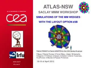
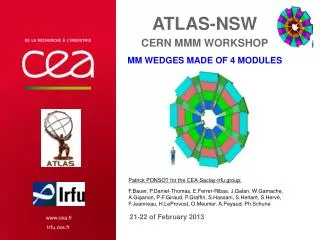
ATLAS-NSW FRASCATI MMM workshop Saclay plan . Patrick PONSOT for the CEA-Saclay-Irfu group: F.Bauer, P.Daniel-Thomas, E.Ferrer-Ribas, Ch.Flouzat, J.Galan, W.Gamache, A.Giganon, P-F.Giraud, P.Graffin, S.Herlant, S.Hervé, F.Jeanneau, H.LeProvost, O.Meunier, A.Peyaud, Ph.Schune.

E N D
ATLAS-NSWFRASCATI MMM workshopSaclay plan Patrick PONSOT for the CEA-Saclay-Irfu group: F.Bauer, P.Daniel-Thomas, E.Ferrer-Ribas, Ch.Flouzat, J.Galan, W.Gamache, A.Giganon, P-F.Giraud, P.Graffin, S.Herlant, S.Hervé, F.Jeanneau, H.LeProvost, O.Meunier, A.Peyaud, Ph.Schune 29-30th of November 2012
OUTLINE • Design ideas • Saclay’s baseline / size of the wedges (quadruplets) • Possible mechanical design of a quadruplet • Dedicated frame to fix the mesh and the drift electrode • Positioning of the doublets • Alignable ? • Materials • Proposal to build an operational quadruplet • Learning about procedures (gluing, positioning,…etc.) • Checking all parameters (precision, in-plane alignment, electronics, RO mapping, services…etc.) • Assembly ideas • Assembly procedure of the quadruplets (some remarks) • Assembly of the quadruplets to form a wedge, a station, a sector ? • In-plane alignment ? • Mechanical prototypes and task sharing • Objectives • Control of the geometry (precision of the construction) • Control of the deformation (in-plane alignment) • Behavior of a doublet (with and without pillars) ? • FEA - Thermo-mechanical simulations • Schedule and sharing of work Frascati MMM workshop - CEA-Saclay/DSM/Irfu - Patrick PONSOT
OUTLINE • Design ideas • Saclay’s baseline / size of the wedges (quadruplets) • Possible mechanical design of a quadruplet • Dedicated frame to fix the mesh and the drift electrode • Positioning of the doublets • Alignable ? • Materials • Proposal to build an operational quadruplet • Learning about procedures (gluing, positioning,…etc.) • Checking all parameters (precision, in-plane alignment, electronics, RO mapping, services…etc.) • Assembly ideas • Assembly procedure of the quadruplets (some remarks) • Assembly of the quadruplets to form a wedge, a station, a sector ? • In-plane alignment ? • Mechanical prototypes and task sharing • Objectives • Control of the geometry (precision of the construction) • Control of the deformation (in-plane alignment) • Behavior of a doublet (with and without pillars) ? • FEA - Thermo-mechanical simulations • Schedule and sharing of work Frascati MMM workshop - CEA-Saclay/DSM/Irfu - Patrick PONSOT
Introduction • A report has been written to describe the Saclay’s plan for the mechanical architecture of the micromegas wedges Frascati MMM workshop - CEA-Saclay/DSM/Irfu - Patrick PONSOT
DESIGN IDEAS • Saclay’s baseline = 2 Wedges made of 4 Modules with maximum size ~2m2 • As reminder : MM Module = Quadruplet = 4 planes in Z direction • Why ? • We think that it is not possible to reach the perpendicular required precision of the strips by assembly of 4 planes with a very large area (large sector ~6m2) • In spite of a lot work, we never reached this range of precision during the construction of the ALICE muon panels (carbon fibers panels) • Using our experience on CTA mirror (very recent tests), we think that we can reach the precision for a 2m2 area • At the end we need : • sMM < 100 mm (micro-TPC mode) • strip parallelism: ≤ 40 mm • Mechanical precision perpendicular to strip plane: • <150 mm at 15° (inner quadruplets) • < 80 mm at 30° (outer quadruplets) Views on next slides • Very complicated to realize the 2D read-out mapping and to connect the Y strips through the full length of the wedge (~3.7m) Frascati MMM workshop - CEA-Saclay/DSM/Irfu - Patrick PONSOT
DESIGN IDEAS • Saclay’s baseline = 2 Wedges made of 4 Modules with maximum size ~2m2 • As reminder : MM Module = Quadruplet = 4 planes in Z direction • Why ? • From our experience: CTA mirrors (Carbon, G10, Al.) MM Compass (G10) MM T2K (G10) Alice / Carbon panels Frascati MMM workshop - CEA-Saclay/DSM/Irfu - Patrick PONSOT
DESIGN IDEAS • Possible mechanical design of a quadruplet (scheme) • Central panel is the mechanical support (thickness at least 20mm to define by FEA, and to test with prototypes) Fixation (and gluing?) of the mesh frame Possible to put an interface to connect the supports If needed, pillars Doublet At least ~20mm At least ~75mm (Not up to date) Doublet This part of the central panel can be local or all along the sector Assembly of the quadruplet after positioning of the 2 doublets Mechanical reference system to position the 2 doublets (metallic inserts) Frascati MMM workshop - CEA-Saclay/DSM/Irfu - Patrick PONSOT
DESIGN IDEAS • Possible mechanical design of a quadruplet (scheme) • Supporting of 2 quadruplets, in-plane alignment system → Local links (to confirm by FEA) (Not up to date) In plane alignment to connect the 2 quadruplets The 2 MM wedges are linked by local supports (kinematic links) At least ~225mm ~75mm Bar support to link the 4 modules (Not up to date) Local supports Frascati MMM workshop - CEA-Saclay/DSM/Irfu - Patrick PONSOT
DESIGN IDEAS • Possible mechanical design of a quadruplet (scheme) • Supporting of 2 quadruplets, in-plane alignment system → If local links are not enough, by using a spacer-frame (Not up to date) In plane alignment to connect the 2 quadruplets The 2 MM wedges are linked by a spacer-frame (kinematic links, holes to have access to the electronic) At least ~225mm ~75mm The 3 kinematics supports can be fixed on the spacer-frame (Not up to date) Frascati MMM workshop - CEA-Saclay/DSM/Irfu - Patrick PONSOT
DESIGN IDEAS • Possible mechanical design of a quadruplet (scheme) • Dedicated frame to fix the drift cathode and the mesh ? • A transfer frame can be used for mounting Fixation (and gluing?) of the mesh frame Cathode made of kapton or mylar + Copper or al. (Not up to date) Mesh Transfer frame to maintain the tension inside the mesh and cathode Frascati MMM workshop - CEA-Saclay/DSM/Irfu - Patrick PONSOT
DESIGN IDEAS • Possible mechanical design of a quadruplet (scheme) • Positioning of the 2 doublets • By using metallic inserts glued with high precision during the construction of the doublets • Targets reference on PCBs to glue the inserts and to check the alignment of the 2 doublets • Z positioning of the doublets is done also by using the inserts (on doublets and on central panel, precise thickness) (Not up to date) Assembly of the quadruplet after positioning of the 2 doublets Mechanical reference system to position the 2 doublets (metallic inserts) Frascati MMM workshop - CEA-Saclay/DSM/Irfu - Patrick PONSOT
DESIGN IDEAS • Possible mechanical design of a quadruplet (scheme) • Alignable (in-plane alignment is on the outside panel) ? • How can we guaranty that the stiffness of the doublets is enough to control the Z position of the strips inside a quadruplet (// of the doublets after deformation due to thermo-mechanical loading) ? • Testing is needed to know the relative deformation of each panel inside a quadruplet • If result is negative, pillars (or other spacer) should be glued in the drift gap (40 pillars diameter 5mm is less than 0.2% of the detection area) • More difficult to glue the pillars with separate mesh (no bulk), and with separate drift cathode Deformation with thermal loading is not symmetric No bulk If needed, pillars 5 mm Gluing on few additional and larger pillars ? (Not up to date) // strips 5 mm Bulk Frascati MMM workshop - CEA-Saclay/DSM/Irfu - Patrick PONSOT
DESIGN IDEAS • Possible mechanical design of a quadruplet (scheme) → Materials • Honeycomb should be perforated (or porous) to use the vacuum pumping for gluing • Very important parameter : ageing of the material should be studied before to use them (e.g. zebra connectors are made of silicon elastomer which has a bad withstand to radiation) • Tensile tests in 3 directions to evaluate the Young modulus of the PCBs has been done at Saclay • L (length direction) → 24 Gpa • l (width direction) → 21 Gpa • p (45°) → 17 Gpa Frascati MMM workshop - CEA-Saclay/DSM/Irfu - Patrick PONSOT
OUTLINE • Design ideas • Saclay’s baseline / size of the wedges (quadruplets) • Possible mechanical design of a quadruplet • Dedicated frame to fix the mesh and the drift electrode • Positioning of the doublets • Alignable ? • Materials • Proposal to build an operational quadruplet • Learning about procedures (gluing, positioning,…etc.) • Checking all parameters (precision, in-plane alignment, electronics, RO mapping, services…etc.) • Assembly ideas • Assembly procedure of the quadruplets (some remarks) • Assembly of the quadruplets to form a wedge, a station, a sector ? • In-plane alignment ? • Mechanical prototypes and task sharing • Objectives • Control of the geometry (precision of the construction) • Control of the deformation (in-plane alignment) • Behavior of a doublet (with and without pillars) ? • FEA - Thermo-mechanical simulations • Schedule and sharing of work Frascati MMM workshop - CEA-Saclay/DSM/Irfu - Patrick PONSOT
PROPOSAL to build a quadruplet • Building an operational quadruplet (~1m x ~0.5m) within the collaboration • Not a critical milestone • But necessary part of the Saclay’s development plan to prove to the CEA-Saclay-Irfu management team that the assembly of 4 MM planes will be completely understood before the construction of a module zero (to get resources to prepare the production) • Objectives • Learning about procedures (gluing, positioning,…etc.) • Checking all parameters (precision, in-plane alignment, electronics, RO mapping, services…etc.) • Testing inside a precise cosmic bench Frascati MMM workshop - CEA-Saclay/DSM/Irfu - Patrick PONSOT
PROPOSAL to build a quadruplet • Building an operational quadruplet (~1m x ~0,5m) within the collaboration • Not a critical milestone • This prototype will allow checking of the: • design and manufacturing of the components • assembly procedure • mechanical precision • in-plane alignment method • 2D read-out mapping • electronics implementation • cosmic tests • services (HV, gas, …) • … • To be discussed within the collaboration: • Tasks sharing within the collaboration • Parallel testing ? • Using of existing precise cosmic bench Frascati MMM workshop - CEA-Saclay/DSM/Irfu - Patrick PONSOT
OUTLINE • Design ideas • Saclay’s baseline / size of the wedges (quadruplets) • Possible mechanical design of a quadruplet • Dedicated frame to fix the mesh and the drift electrode • Positioning of the doublets • Alignable ? • Materials • Proposal to build an operational quadruplet • Learning about procedures (gluing, positioning,…etc.) • Checking all parameters (precision, in-plane alignment, electronics, RO mapping, services…etc.) • Assembly ideas • Assembly procedure of the quadruplets (some remarks) • Assembly of the quadruplets to form a wedge, a station, a sector ? • In-plane alignment ? • Mechanical prototypes and task sharing • Objectives • Control of the geometry (precision of the construction) • Control of the deformation (in-plane alignment) • Behavior of a doublet (with and without pillars) ? • FEA - Thermo-mechanical simulations • Schedule and sharing of work Frascati MMM workshop - CEA-Saclay/DSM/Irfu - Patrick PONSOT
ASSEMBLY IDEAS • Assembly procedure of the quadruplets (some remarks) • Due to experience of the institutes, we think that it is accessible to define precise tooling and procedures to build and to align the components but we will use a new material → large PCBs made of composite materials: G10, pyralux, copper…etc. • Gluing procedure by using vacuum should be tested with real PCBs as soon as possible to answer to the following questions : • What is the best choice for materials to control the geometry during the production (stability, reproducibility) ? • Will the PCBs follow the granite table flatness ? • Will the PCBs stay flat after gluing of the honeycomb (temperature and humidity inside the cleaning room to do the gluing) ? • Do we get the // for the doublets by using the stiffback ? Frascati MMM workshop - CEA-Saclay/DSM/Irfu - Patrick PONSOT
ASSEMBLY IDEAS • Assembly procedure of the quadruplets or wedges (some remarks) • A preliminary study has been done to evaluate the infrastructures and tooling that is needed to build quadruplets • The building of the second ring of quadruplets has been used as main hypothesis to do this study • We need a large cleaning room to do all the steps (2 gluing tables, 3 assembly tables) • Unfortunately, the Saclay’s cleaning rooms are not available on 2013-2014. And we are not sure to get a new one. The construction of the operational quadruplet prototype will influence also the final decision • We need one year to create a new cleaning room • It is very important to take in account the infrastructures that we need to define the size of the modules that we can build (wedges ~6m2 or quadruplets ~2m2) • May be the assembly should be done at CERN in a large cleaning room with participation of institutes Preliminary study to define a new infrastructure Frascati MMM workshop - CEA-Saclay/DSM/Irfu - Patrick PONSOT
ASSEMBLY IDEAS • Assembly of quadruplets to form a wedge, a station, a sector ? • MM Wedges vs MM quadruplets • sTGC wedges can be added with the same principle ~1.89 m2 ~5.87m2 ~1.85 m2 ~1.33 m2 ~0.80 m2 3 kinematic supports to fixe the spacer-frame 3 kinematic supports to fixe the 2 wedges Frascati MMM workshop - CEA-Saclay/DSM/Irfu - Patrick PONSOT
ASSEMBLY IDEAS • In-plane alignment system • To be defined with specialists • In-plane with 2 functions (to follow the 2 wedges) 3 kinematic supports to fixe the spacer-frame 3 kinematic supports to fixe the 2 wedges Frascati MMM workshop - CEA-Saclay/DSM/Irfu - Patrick PONSOT
OUTLINE • Design ideas • Saclay’s baseline / size of the wedges (quadruplets) • Possible mechanical design of a quadruplet • Dedicated frame to fix the mesh and the drift electrode • Positioning of the doublets • Alignable ? • Materials • Proposal to build an operational quadruplet • Learning about procedures (gluing, positioning,…etc.) • Checking all parameters (precision, in-plane alignment, electronics, RO mapping, services…etc.) • Assembly ideas • Assembly procedure of the quadruplets (some remarks) • Assembly of the quadruplets to form a wedge, a station, a sector ? • In-plane alignment ? • Mechanical prototypes and task sharing • Objectives • Control of the geometry (precision of the construction) • Control of the deformation (in-plane alignment) • Behavior of a doublet (with and without pillars) ? • FEA - Thermo-mechanical simulations • Schedule and sharing of work Frascati MMM workshop - CEA-Saclay/DSM/Irfu - Patrick PONSOT
MECHANICAL PROTOTYPES • Objectives • Control of the geometry (precision of the construction) • Control of the deformation (to define the in-plane alignment) • Study of the geometry of a doublet • Stiffness of the composite panel (PCBs + honeycombs + frames) • Gluing test of 2 PCBs on the honeycomb (vacuum) • Using of a composite stiffback • Saclay’s plan: • Gluing of honeycomb on standard PCBs to evaluate the stiffness of a support panel • Gluing of honeycomb on large MM PCBs (paper honeycomb, perforated aluminum honeycomb…etc.) • Options: • Sharing of the tasks and parallel testing with real PCBs (bulk & no bulk ?) Frascati MMM workshop - CEA-Saclay/DSM/Irfu - Patrick PONSOT
MECHANICAL PROTOTYPES • Study of the deformation of a quadruplet • FEA to predict the deformations: to choose the size of the mechanical prototype • Measurement without and with pillars • Mechanical and thermal loadings • Saclay’s plan: • Construction of mechanical structure equivalent to a MM doublet (G10 + honeycomb) • Dismountable to test without and with pillars • Holes in the external panels allow mechanical measurements on the central panel • Assembly with and without expandable pins to study the effect of the sliding of the frames • Options: • To build an equivalent quadruplet (5 panels) • To build an assembly of 2 doublets (2x3 panels) • To use other materials (e.g. aluminum honeycomb, PCBs…etc.) Frascati MMM workshop - CEA-Saclay/DSM/Irfu - Patrick PONSOT
MECHANICAL PROTOTYPES • Study of the gluing of pillars • Qualification of the gluing • Choice of material for the pillars (Macor, peek…) • Saclay’s plan: • Tooling is under manufacturing • 200 pillars have been ordered (Macor, peek, different geometry to put the glue) • Options: • Testing of other solutions and materials to guarantee a similar behavior of each MM plane after stacking Frascati MMM workshop - CEA-Saclay/DSM/Irfu - Patrick PONSOT
MECHANICAL PROTOTYPES • Study of the positioning inside a quadruplet • As described on slide 11 (positioning of the 2 doublets) • Saclay’s plan: • Building of a simplified quadruplet (e.g. with the doublets created during other tests) • Options: • Parallel testing • Other solution such as optical systems sTGC proposal Frascati MMM workshop - CEA-Saclay/DSM/Irfu - Patrick PONSOT
Thermo-mechanical simulations • FEA analysis • Preliminary FEA analysis have been done to: • provide arguments in order to make a decision concerning the layout • Identify the main cause of irregular deformation → thermal loading • We need engineering models to: • Confirm that we can control the geometry with the alignment system according to the different options (quadruplets, wedges, stations, sectors…) Temperature gradient 2°C ~50µm Thermal expansion MM+sTGC ~100µm Frascati MMM workshop - CEA-Saclay/DSM/Irfu - Patrick PONSOT
Thermo-mechanical simulations • FEA analysis • Preliminary study of the behavior of a mixed sector (sTGC wedges + MM quadruplets fixed on a spacer frame) w.r.t. the position on the small wheel • In this case, MM deformation is around ~100µm Vertical sector Sector at 45° If we are not able to measure this type of deformation with the alignment system, we must guaranty that we will stay under these 100µm Horizontal sector Frascati MMM workshop - CEA-Saclay/DSM/Irfu - Patrick PONSOT
Schedule and sharing of work • Preliminary schedule • Help from collaboration is needed and is welcome : Task and cost sharing • To participate to this program and/or to complete it Frascati MMM workshop - CEA-Saclay/DSM/Irfu - Patrick PONSOT
Conclusion • Sharing of work and parallel testing within the collaboration are welcometo cover this plan as soon as possible • Mechanical tests • FEA analysis • Operational quadruplet • In-plane alignment • Assembly of the quadruplets or wedges • The largest cleaning rooms at Saclay will not be available on 2013-2014 • The possibility to use a cleaning room at CERN should be evaluate Frascati MMM workshop - CEA-Saclay/DSM/Irfu - Patrick PONSOT
Thank you for your attention ! Commissariat à l’énergie atomique et aux énergies alternatives Centre de Saclay| 91191 Gif-sur-Yvette Cedex T. +33 (0)1 69 08 79 30 | F. +33 (0)1 69 08 89 47 Etablissement public à caractère industriel et commercial | RCS Paris B 775 685 019 DSM IrfuSIS/LCAP (PC N°12, Bt 123)Patrick PONSOT Frascati MMM workshop - CEA-Saclay/DSM/Irfu - Patrick PONSOT