Download
1 / 31
310 likes | 410 Views
Explore different views in UML, such as Use-Case, Logical, Component, and Deployment, to understand system architecture and design. Learn through diagrams like Use-Case, Sequence, and Collaboration, along with key notations and types in the Unified Modeling Language.

E N D
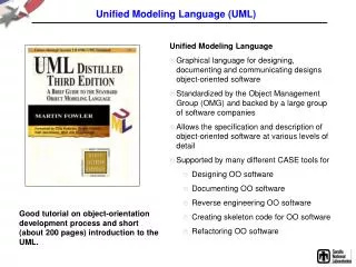
UML • The static structure defines the kinds of the objects important to a system and to its implementation as well as relationship among the objects. • The dynamic behaviour defines history of the objects over time and the communication among the objects to accomplish task.
UML – some notation • Object classes are rectangles with the name at the top, attributes in the middle section (“compartment”) and operations in the next compartment. • Relationships between object classes (known as associations) are shown as lines linking objects • Inheritance is referred to as generalisation. • It uses an open triangular arrow head
UML diagrams • Structural View • Class Diagram • Object Diagram • Behavioral View • Sequence Diagram • Collaboration Diagram • State-chart Diagram • Activity Diagram • User’s View • Use Case • Diagram • Implementation View • Component Diagram • Environmental View • Deployment Diagram
The use-case view The use-case view helps you to understand and use the system. This view looks at how actors and use cases interact. The diagrams in this view are: • Use-case diagrams • Sequence diagrams • Collaboration diagrams • Activity diagrams
The use-case view • This view contains a Main diagram by default. Additional diagrams can be added throughout the analysis and design process.
The logical view The logical view addresses the functional requirements of the system. This view looks at classes and their relationships. The diagrams in this view are: • Class diagrams • Statechart diagrams
The logical view • This view contains a Main diagram by default. Additional diagrams can be added throughout the analysis and design process.
The component view The component view addresses the software organization of the system. This view contains information about the software, executable and library components for the system. This view contains only component diagrams.
The component view • The component view contains a Main diagram by default. Additional diagrams can be added to this view throughout
The deployment view The deployment view shows the mapping of processes to hardware. This type of diagram is most useful in a distributed architecture environment where you might have applications and servers at different locations. This view contains only one diagram – the deployment diagram.
Use case diagrams show the interaction of users of the system with the functionality of the system. A use case is a functional component of the system that accomplishes a specific task, and is represented by an ellipse. An actor, depicted as a stickman figure, is a user of the system performing a specific role. Use Case Diagrams
Types of Actors in use case diagram: • Primary Actors: • People who use the main system functions. • Secondary Actors • People that perform administration or maintenance tasks. • Other systems: • The others systems with which the system must interact.
Use Case Diagrams • Use case diagrams are used early in the development process to refine the functional specifications, identify user interface requirements, and to define the scope of the project.
Use-case diagrams • Use-case diagrams present a high-level view of system usage as viewed from an outsider’s (actor’s) perspective. • These diagrams show the functionality of a system or a class and how the system interacts with the outside world. • Use-case diagrams can be used during analysis to capture the system requirements and to understand how the system should work.
Use-case diagrams • During the design phase, use-case diagrams specify the behavior of the system as implemented. • Rose automatically creates a Main use-case diagram in the use-case view. • There are typically many use-case diagrams in a single model. • Use case model represents the external view of system.
Types of Use-case 1.Including Use Cases: • Use cases may contain the functionality of another use case as part of their normal processing. • In general it is assumed that any included use case will be called every time the basic path is run. • An example of this is to have the execution of the use case<Card Identification> to be run as part of a use case <Withdraw>.
1.Including Use Cases: • Use Cases may be included by one or more Use Case, helping to reduce the level of duplication of functionality by factoring out common behavior into Use Cases that are re-used many times.
2.Extending Use Cases • One use case may be used to extend the behavior of another; • this is typically used in exceptional circumstances.
2.Extending Use Cases • For example, if before modifying a particular type of customer order, a user must get approval from some higher authority, then the <Get Approval> use case may optionally extend the regular <Modify Order> use case.
Extension , Specialization Of Use Cases • Extensions: • When the user is expected to make the optional interactions or to handle an exceptional condition, then the base use case is more or less valid, but needs further extensions by way of addition or minor modifications to complete the actor’s request. • We create a separate use case limited to the deviation sought in the original use case . • Extension are to be designed for handling exceptional , one off request of the users.
Extension , Specialization Of Use Cases • Example: In example of railway ticket booking , it is not expected that the passenger would change the ticket choice from ‘ Chair Car ‘ to ‘Sleeper Car’. But at the very last moment , if the choice is changed to Sleeper Car , the use of the extension use case will be different for ticket printing and related process only.
Extension , Specialization Of Use Cases • Specialization: • When an analysis is made of scenario , we will; come across use case that need to be included in the system. • In some cases, we will come across the situation where the use case scope is common to some extent that the preconditions and processes within the use case and post conditions are common across all users. • But in the same use case, we need to handle a special scenario where most of the specifications are common to the special case as well.
Extension , Specialization Of Use Cases Ticketing Book Passenger Extension Specialization Ticket Booking with Concession Journey and Tariff Special conditions Extension with Concession in fare Passenger from Military Services
Use Case Diagram Example Figure 1.9: Use Case diagram for an Automated Teller Machine (ATM) system
Use Case Diagram Example • This Use Case diagram shows the interactions between the use cases and actors of an ATM system. • In this example, the bank's customer initiates a number of use cases: Withdraw Money, Deposit Funds, Transfer Funds, Make Payment, View Balance, and Change PIN. • A few of the relationships are worthy of further mention. • The bank officer can also initiate the Change PIN use case. • The Make Payment use case shows an arrow going to the credit system.
Use Case Diagram Example • External systems may be actors and, in this case, the credit system is shown as an actor because it is external to the ATM system. • The arrow going from a use case to an actor illustrates that the use case produces some information that an actor uses. • In this case, the Make Payment use case provides credit card payment information to the credit system.
Benefits Of Use Case • Ensures complete system documentation, as all use cases are included with model , design and details. • Reduce the user’s need for training and hand-holding in learning to operate the system. • Use system more efficiently. • Reduce the time for system maintenance. • Obtain user’s fast acceptance of the system.