ISO 11783 Task Controller
ISO 11783 Task Controller. Lecture 9 Task Controller – Part 2 ISO 11783 Part 10 BAE 5030 - 353 Spring 2009 Instructor: Marvin Stone Biosystems and Agricultural Engineering Oklahoma State University. Taken largely from: Andy Beck and Hans Nissen John Deere and Co.

ISO 11783 Task Controller
E N D
Presentation Transcript
ISO 11783 Task Controller Lecture 9 Task Controller – Part 2 ISO 11783 Part 10 BAE 5030 - 353 Spring 2009 Instructor: Marvin Stone Biosystems and Agricultural Engineering Oklahoma State University Taken largely from: Andy Beck and Hans Nissen John Deere and Co. NAIITF ISOBUS Task Controller Workshop 4 June 2008 BAE 5030-353
Device Configuration Data (DCD) • Also referred to as Device Description Data (DDD) • The DCD describes the connected Working Set for the TC and Desktop SW • Number of bins (tanks), booms, sections • the structural relationship between the objects (sections are children to a boom, etc) • the offsets of the objects to each other (x-, y-, z-offset) • which Process Data Variables a particular DCD element supports • (e.g. boom supports on/off status and current application rate) • version, embedded language and unit settings (localization label) • A valid DCD has to be available per Working Set for a standard TC communication • either as runtime upload via CAN at system start-up • or offline via import into Desktop SW BAE 5030-353
Device Configuration Data (DCD) • Also referred to as Device Description Data (DDD) • The DCD describes the connected Working Set for the TC and Desktop SW • Number of bins (tanks), booms, sections • the structural relationship between the objects (sections are children to a boom, etc) • the offsets of the objects to each other (x-, y-, z-offset) • which Process Data Variables a particular DCD element supports (e.g. boom supports on/off status and current application rate) • version, embedded language and unit settings (localization label) • A valid DCD has to be available per Working Set for a standard TC communication • either as runtime upload via CAN at system start-up • or offline via import into Desktop SW BAE 5030-353
Device Descriptor Object Pool BAE 5030-353
Device Element Object (DET) • Each DCD has to have one DET object of type Device representing the machine • Multiple objects of type DET represent the machine functions • Device Element Objects (DETs) • Object Fields: • Object ID • Object Designator (string may be displayed by the TC) • Device Element Types • Device – represents the overall machine (e.g. sprayer) • Function – generic object to represent sensors, booms, etc • Bin – Sprayer tanks or planter bins, etc • Section – represents individual row units for planters, sprayers, etc • Unit – Sub-units of Sections (e.g. nozzles of a sprayer section) • Connector – Connection point between different WS (e.g. at the back of the tractor and at the front of the drawbar) • Nav. Ref. Point – Mounting location for GPS receivers etc • Device Element Number -individual number used to identify this object in the PDM • Parent Device Element ID (section objects point to their boom etc) • List Object IDs of Child Objects BAE 5030-353
Device Object (DVC) • Each DCD has to have one DVC object • Represents the overall DCD • Object Fields: • Object ID • Object Designator (string may be displayed by the TC) • Software Version of the related application • NAME of owning WS Master • Serial Number of WS Master • Structure Label (Proprietary information about the machine configuration represented by the DCD) • Localization Label (Unit and Language settings represented by the DCD) BAE 5030-353
Device Process Data Object (DPD) • DPD objects represent the values (DDI) supported by the parent object for recording etc, e.g. • current application rate • application rate set-point (for prescription) • on/of status • Object Fields: • Object ID • Object Designator (string may be displayed by the TC) • Process Data Element ID (DDI as specified in part 11 dB) • Process Data properties • DDI is set-able => the TC can prescribe this value • DDI is part of ‘Default Data Set’ of this WS • Supported Trigger Methods • time and distance interval • min and max threshold limits • on-change • total counter • Reference to Device Value Presentation Object (Object ID) BAE 5030-353
Device Property Object (DPT) • DPT objects represent fixed values which don’t change during operation; e.g. • x-, y-, z-offsets • bin-size • Object Fields: • Object ID • Object Designator (string may be displayed by the TC) • Process Data Element ID (DDI as specified in part 11 dB) • Property Value (actual fixed value of this DDE) • Reference to Device Value Presentation Object (Object ID) BAE 5030-353
Device Value Presentation Object (DVP) • DVP objects define how the value of the parent object may be displayed to the operator in terms of units, value scaling, etc • Object Fields: • Object ID • Object Designator (string may be displayed by the TC) • Offset to be applied before displaying the value • Scale to be applied before displaying the value • Number of Decimals (number of digits behind decimal point) • Unit Designator String BAE 5030-353
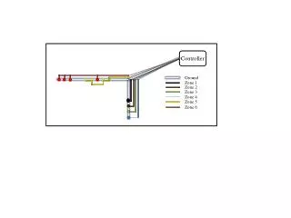
Device Geometry - Plan View BAE 5030-353
Device Geometry - Side View x-axis is specified as positive - in normal driving direction y-axis is specified as positive - to the right of the normal driving direction z-axis is specified as positive - downward towards the ground BAE 5030-353
Data Dictionary Element (DDE) • Defined in the online database of part 11 (see www.isobus.net) • Includes the following information • Unique Identifier (DDI) • Clear definition • Unit definition • Value Range • Resolution • Diagnostic information (SPN) • Comments • Device Class supported by the DDE • Database allows all DDE’s to be downloaded into an Excel Spreadsheet • Requests for new DDE’s are evaluated and assigned by an international Expert Team BAE 5030-353