Download
1 / 42
420 likes | 531 Views
This senior thesis presents the structural redesign of the Gateway Commons project, a mixed-use development located at 311 E. Green Street, Ithaca, NY. The project spans ten stories, incorporating 2 retail units and 25 residential spaces, totaling 43,000 square feet with a budget of $7.4 million. The thesis addresses the limitations of the existing structure while proposing an economical and flexible design that utilizes a one-way concrete system. Key aspects include enhanced live load capacities and efficient column layouts, ensuring both structural integrity and architectural versatility.

E N D
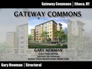
Gateway commons Gary Newman Structures Option Advisor: Dr. Hanagan Senior Thesis Presentation Spring 2008
Upscale, mixed use development • 62’ - 6 stories • 2 retail and 25 residential spaces. • 43,000 square feet • $7.4 million • December 2005 – April 2007 • Façade of brick, EIFS, and metal panels introduction • 311 E. Green Street Ithaca, NY • Located in between downtown area • and nature area
Existing Structure - walls • 8” CMU walls • Reinforced with #5 bars at 4’ o.c. • with standard joint reinforcing • Fully grouted 1st - 2nd floors • All wall types are gravity load • bearing only MW2 and MW3 are • part of lateral system
Existing Structure - floors • Precast concrete hollow core plank • First floor 10” thick, 2” topped planks • 2nd – 6th floor 8” thick, un-topped planks • Slab on Grade • 5” thick SOG, f’c = 3,500 psi • #4 @ 16” o.c. both ways
Existing Structure – lateral system • 13 intermediate reinforced masonry shear walls • 8” CMU reinforced like MW1 except includes boundary elements
Existing Structure - foundations • Walls supported by strip footing, f’c = 3000 psi • 1’-4” thick concrete retaining walls, f’c = 4000 psi • Soil with allowable bearing capacity of 5,000 psf
Problem Statement • The existing structure is the best choice for the building’s use • Tech 2 showed existing system to be cheapest compared to steel and • concrete structures • Custom structure • If a change in the architecture of the building was to be considered the large • amount of load bearing walls would make an effective redesign of the • architecture almost impossible.
Proposed Solution • A structural system that used columns would allow for a more open structure • A two way concrete system was first proposed but it was too difficult to • determine a feasible column layout • A one way concrete structure was determined to be the best structure
Proposed Solution • Goals • To gain a better understanding of concrete structures and the engineering • design process • To create a complete and economical structural redesign of Gateway Commons • To compare the new structure to the old one • To architecturally design the new structure for an office building to show that • the new structure allows for versatility in architectural redesign • To determine the cost and schedule of the new structure and determine if the • redesign is economically feasible
Structural Redesign - Slab • SOG on first floor and basement are the same as in • original design • Pan joist slab is good for long spans with relatively • light loads • Live load increases from 40 psf to 80 psf to allow for • office redesign • f’c = 5000 psi • 4.5” top slab to provide 2 hour fire rating
Structural Redesign - Slab • Representative design strips of the slab were • designed for in PCA slab • Bar size, spacing and cut off point used in • slab design • 7”x 10” ribs spaced at 20” were determined • to withstand the slab shear capacity and • deflections • #4 for top slab and between #4 - #6 for ribs
Structural Redesign - Slab • The roof will use the same slab dimensions as the floors and the roof • will continue over 6th floor terrace • 4” thick roof overhangs either cantilevered from beam or was • designed as a slab between cantilevered beams
Structural Redesign - girders • Girders designed as continuous beams • Width of girders restricted by mechanical openings • and hallways • Depth controlled by deflection: • Top & Bottom = 14”x 16” Middle = 14”x 18” • f’c = 5000 psi
Structural Redesign - girders • Continuous beams were modeled in SAP • Design moments for flexure determined by use of pattern loading • Continuity of slab puts compatibility torsion on the beams • Moment coefficients were used to determine the net moment the slab puts • on the girders
Structural Redesign - girders • Flexure and shear/torsion reinforcement was calculated by hand
Structural Redesign - columns • Floor to floor height is 11’ • Column height will be 9’-6” for 16” deep girders and 9’-8” for 18” deep girders • Column dimensions are 14”x 24”, f’c = 5000 psi • SAP model used to determine axial and moment on each column • Applied to PCA column as factored loads • Majority of columns use (4) #9. Largest amount of reinforcement is (6) #10
Structural Redesign – Lateral system • WIND • Basic Wind Speed 90 mph • Exposure category B • Base shear N-S = 165.2 kips Base shear E-W = 86.7 kips • SEISMIC • Site class D • Seismic Design Category B • R = 5 • Base Shear = 120 kips
Structural Redesign – Lateral system • Shear walls are located around the stair towers • 8” thick ordinary reinforced concrete shear walls • f’c = 5000 psi
Structural Redesign – Lateral system • Shear and flexure ETABS models were created • In the shear model, each wall is assigned its own pier label • In the flexure model, walls that connect are assigned the same pier label
Structural Redesign – Lateral system • Shear forces on each wall were factored • and used to design for shear reinforcing • Moment and axial loads were used to • design for flexure reinforcement. • In PCA column flexure forces were input • as service loads and load combinations • were created • Large part of wall design carried into small • section over door opening and (2) #5 • around opening per ACI 22.6.6.5 • Horizontal shear reinforcing is #4 @ 18” • Vertical reinforcing controlled by flexure • and is mostly #4 @ 18” • Pier 3 in flexure model designed as an • isolated wall and required an increase in • reinforcement
Structural Redesign – Lateral system • The eccentricity between the COR and COM was not very large so • torsion was added to direct shear • Allowable story displacement h/400 = 1.98” • All displacement values less than 1”
Structural Redesign - foundations • 9’x 9’x 3’ spread footings for the columns • Retaining walls will use the same dimensions and reinforcing • Columns are integrated with retaining walls • Slab on first floor is supported by retaining walls
Structural Redesign - foundations • Strip footings will be used for the shear walls and the retaining walls • Footings will have an f’c = 3000 psi • Retaining walls will have an f’c = 4000 psi
Architecture breadth • Where columns are placed on windows the windows can be moved • and the architecture will still work.
Architecture breadth • A roof will be placed over the 6th floor roof terrace in the redesign of • the structure • This will be done to allow for this area to have more versatility in a • redesign of the architecture • The area that was the 6th floor terrace will be able to be redesigned as a • community gathering place that is open to the outdoors.
Construction Management breadth • COST • Cost of existing structure = $2,078,841 • Cost of new structure = $1,293,136 • Total savings of $785,705 • RS Means Facilities Construction Cost Data 2006
Conclusion • Pan joist system proved to be compatible with the existing architecture • The structure allows for versatility in architectural redesign • The cost of the structure decreases and the schedule increases according • to my results • I would recommend that Gateway Commons be constructed with the • new pan joist structural system instead of the precast concrete hollow • core plank on CMU walls
Acknowledgments The AE faculty Friends and Family Ryan Biggs Associates Northeast Construction