Download
1 / 43
1.43k likes | 3.31k Views
Lightning and Surge Protection according to IEC 62305. Damage due to Lightning and Surges. ABC Company. MCR. 2 km. Danger due to Lightning Strokes. approx. 1,900,000 lightning strokes in Germany per year*. data. telephone. 110 kV. mobile phone. 400/230 V. TV.

E N D
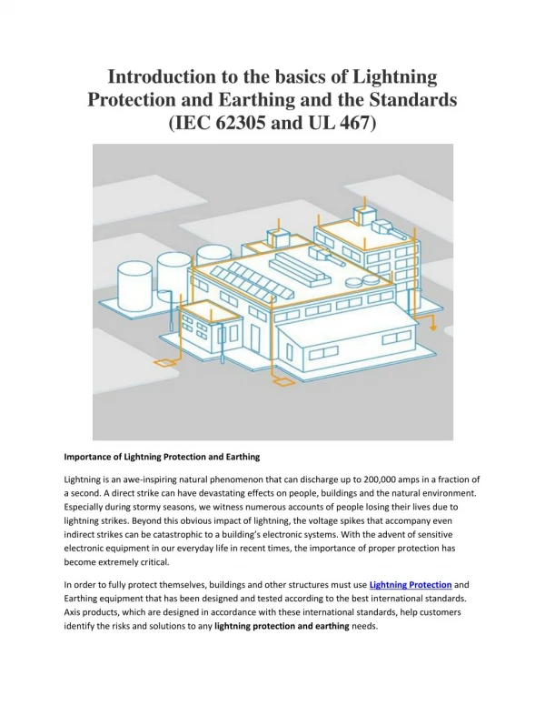
Lightningand Surge Protectionaccordingto IEC 62305 Lightning and Surge Protection
Damage due toLightningandSurges Lightning and Surge Protection
ABC Company MCR 2 km Danger due to Lightning Strokes approx. 1,900,000 lightning strokes in Germany per year* data telephone 110 kV mobile phone 400/230 V TV *Ref.: BLIDS, Siemens AG, Analysis of 2001 - 2005 Lightning and Surge Protection
Lightning flasches cloud to earth Quelle: http://thunder.msfc.nasa.gov/images/HRFC_AnnualFlashRate_0.5.png Lightning and Surge Protection
Branch-specificCostscausedby a One-hour Loss ofProduction Costsof a one-hour lossofproduction Branch Paper approx. 10,000 € Brewery approx. 10,000 € Car Industry Supplier approx. 12,500 € Power Stations approx. 90,000 € Car Industryapprox. 250,000 € (depending on thesection) Computing Centreapprox. 500,000 € (the potential datalosscannolongerbequantified) Lightning and Surge Protection
Generation andEffects Lightning and Surge Protection
2b 2a 1 Striking of external lightning protection system, process structure (in industrial plants), cables etc. Voltage drop at the implse earthing resistance Rst 1a 1 Induced voltage in loops 1b Distant lightning Strike: Strike into medium- voltageoverheadlines 2c 2a Surge travelling waves on overhead lines due to cloud-to-cloud lightning 2b 1b Rst 1a Fields of the lightning strike 2c Causes of Surges due to Lightning Discharges Direct lightning strike: L1 L2 L3 PEN 20 kV IT network power supply Lightning and Surge Protection
i î t wave form 10 / 350 µs EBB Rst GalvanicCouplingLightningVoltagefor a System Lightning Prot. Level CurrentamplitudekA I 200 II 150 III - IV 100 Ref.: IEC 62305 ûE = î · Rst Example: ûE = 100 kA · 1 = 100 kV Surge Protection
Directlightningstrike (LEMP) • Galvaniccoupling • Inductive / Capacitivecoupling M Influences on ElectricalInstallationsCausesofSurges • Indirectlightningstrike • Conducted partial lightningcurrents • Inductive / Capacitivecoupling • Surges (SEMP) • Switchingoperations • Earth faults / Short circuits • Trippingfuses • Parallel installationof power and IT conductorsystems Lightning and Surge Protection
Lightning Current Parameters according to IEC 62305 Parameters Lightning Protection Level I II III-IV I (kA) 200 150 100 W/R (MJ/) 10 5.6 2.5 Qs (As) 100 75 50 Q long (As) 200 150 100 Lightning and Surge Protection
International Standardisation Lightning and Surge Protection
IEC 62305 International lightningprotectionstandard IEC 62305-1 General Principles IEC 62305-2Risk Management IEC 62305-3PhysicalDamagetoStructuresand Life Hazard IEC 62305-4Electricaland Electronic Systems Lightning and Surge Protection
IEC 62305 International lightningprotectionstandard 62305-1General Principles 62305-2Risk 62305-3Physical damage and life hazard 62305-4Electrical- and electronic systems Lightning and Surge Protection
IEC 62305-2 Risk Management • Byworkingthroughseriesofformulaetheprocessallowstheusertodecidewhatprotectionisrequired. The actualrisk (R) must bebelowthe tolerable level (Rt). • The ultimateprotectionmaybetheinstallationof a LPS system. Directstrikelightningarresters (LEMP) andsurgearresters (SEMP). Lightning and Surge Protection
IEC 62305-3 Physicaldamagetostructuresandlifehazard Introduction a) External LPS (airterminationsystem, down contuctor‘s, earthterminationsystem). b) An internal LPS (preventingdangeroussparkingusingequipotentialbondingorseparationdistance (henceelectricalinsulation) betweenexternal LPS andinternalmetalwork. Lightning and Surge Protection
IEC 62305-4 Electrical- and electronic systemswithinstructures Scope: Providesinformationfor design, installation, inspection, maintenanceandtestingof a LEMP protectionsystem (LPM) forelectricaland electronic systemswithin a structureabletoreduceriskof permanent failure due to LEMP. • Basic protectionmeasures in a LPM system • EarthingandBonding • Magneticshieldingandlinerouting • Directstrikeandsurgeprotection Lightning and Surge Protection
Standardisation of Surge Protective Devices IEC 61643-1Performance Requirementsof Surge Protective Devices for Low-Voltage Power Supply Systems Class IIProtection Against Indirect Lightning Effects (Surge Arrester) (8/20 µs) Class III Protection Against Switching Overvoltages (Surge Arrester) (1.2/50 µs; 8/20 µs) Class IProtection Against Direct Lightning Currents (Lightning Current Arrester) (10/350 µs) Lightning and Surge Protection
ExternalLightningProtection System Air Termination System Downconductor Earth Termination System Lightning and Surge Protection
External Lightning Protection System air termination system down conductor earth termination system Lightning and Surge Protection
EMC-orientatedLightningProtectionZonesConcept Lightning and Surge Protection
LPZ 0 A air-termination system LEMP LPZ 0 B M LPZ 1 LPZ 0 A LEMP down- conductor system LPZ 3 LPZ 2 LEMP LPZ 0 B LPZ 2 LPZ 0 C SEMP foundationearthing electrode steel reinforcement LPZ 1 EMC-Orientated Lightning Protection Zones Concept Lightning equipotential bonding Lightning current arrester (SPD Type 1) Local equipotential bonding Surge arrester (SPD Type 2, SPD Type 3) spatial shield terminal device air ventilation power supply system IT system Lightning and Surge Protection
Internal LightningProtection LightningEquipotentialBonding Surge Protection Coordination Lightning and Surge Protection
Internal Lightning Protection System Based on IEC 62305-4 • Equipotential Bonding at the Boundary of LPZ • Equipotential bonding for all metal parts and supply lines (e.g. metal pipes, electrical power or data lines) which are entering at the boundary of an internal LPZ shall be carried out at equipotential bonding bars which are installed as closely as possible to the point of entry. • SPDs with suitable power carrying capacity for electrical power and data lines at the point of entry into the LPZ have always to be installed. Lightning and Surge Protection
gas Lightning Equipotential Bondingfor incoming Lines lightning equipotential bonding EBB LPZ 0 LPZ 1 power supply external lightning protection system water M heating cathodic protected tank pipe foundation earthing electrode Lightning and Surge Protection
Lightningcurrentarrester Lightning and Surge Protection
Internal Lightning ProtectionSurge Protective Devices Based on IEC 62305-4 Surge protectivedevicesforlightningequipotentialbonding must becapableofsafelycontrollingthe partial lightningcurrentstobeexpectedtoflowthroughthem. Forthispurpose, surgeprotectivedevicesarechosenaccordingtotherequirements on siteandinstalled in accordancewith IEC 60364-5-53 The residual voltageatthesurgeprotectivedeviceinstalledintothebuilding, hastobecoordinatedwiththeimpulsewithstandcapabilityoftheinstallation. Surge protectivedevices Class Itobeinstalledattheentryofthebuilding, keep a significantpartofthepower oflightningcurrentsawayfromtheinsideofthebuilding. Lightning and Surge Protection
What is a Lightning Current Arrester installed into a Power Supply System supposed to perform? • Dischargingoflightningcurrentsseveraltimeswithoutdesctructionoftheequipment.= Dischargecapacity 100 kA (10/350 µs) • Providing of a lowervoltageprotectionlevelthanthevoltagestrengthofthedownstreaminstallation. • Extinguishingorlimitingofmainsfollowcurrents. • Ensuringoftheenergycoordinationtodownstreamsurgeprotectivedevicesand/or terminal equipment. Lightning and Surge Protection
10/350 100 50 2.5 · 106 IEC 62305-1 8/20 5 0.1 0.4 · 103 EN 60060-2 1 1 2 2 1 Test Impulse Curent for Lightning Current Arresters2 Test Impulse Current for Surge Arresters 100 kA Wave form µs] i max. [kA] Q [As] W/R [J/] Standard I (kA) 80 kA 60 kA 50 kA 40 kA 20 kA 20 µs 200 µs 350 µs 600 µs 800 µs 1000 µs t (µs) Lightning and Surge Protection
Overvoltage Categories according to IEC 60364-4-44 Use of Surge Protective Devices (SPD) ratedvoltage withstandvoltage 6 kV 4 kV voltageprotection level 2.5kV 2.5 kV household appliances sensitive devices 1.5 kV 1.5kV terminal device SDB SE M 230/400 V SPD Type 1 2 3 3 (I) (II) (III) (IV) (SPD class) Lightning and Surge Protection
Surge Protection Lightning and Surge Protection
What is a Surge Arrester installed into a Power Supply System supposed to perform? • Dischargingofimpulsecurrents (8/20 µs) severaltimeswithoutdestroyingthe terminal equipment= 20 x nominal dischargecapacity 5 - 20 kA (8/20 µs) • Voltageprotectionlevellowerthantheelectricalstrengthofthedownstream terminal devices= Voltageprotectionlevel 1,500 V Lightning and Surge Protection
Overvoltage Categories according to IEC 60364-4-44 Use of Surge Protective Devices (SPD) rated voltage withstand voltage 6 kV 4 kV voltage protection level 2.5kV 2.5 kV household appliances sensitive devices 1.5 kV 1.5kV terminal device SDB SE M 230/400 V SPD Type 1 2 3 3 (II) (I) (III) (IV) (SPD class) Lightning and Surge Protection
Coordinationof SPDs Lightning and Surge Protection
EnergyCoordinationof SPDs Based on IEC 62305-4 • As soonastwoormore SPDs areconnected in series, thecoordinationofthe SPDs andtheequipmenttobeprotectedhastobechecked. • Energycoordinationisachievedassoonastheratioofenergyfor all impulsecurrentsforeach SPD isequalorlessthancorrespondstoits power withstandcapability. • The power withstandcapabilitycanbedetermined– by an electricaltestaccordingto IEC 61643-1,– fromthetechnicaldataofthemanufacturerofthe SPDs Conclusion: The coordinationofthe SPDs canonlybeverifiedbythemanufacturer! Lightning and Surge Protection
EnergyCoordinationof Surge Protective Devices (SPDs) inputinterference; lightningimpulsecurrent 10/350 µs residual interference impulsecurrent 8/20 µs residual interference uncriticalfor terminal device terminal device ? 230 / 400 V varistor S 20 K 275 DEHNguard ® S DEHNbloc® M DEHNsafe Lightning and Surge Protection
M SDB DEHNventil® M DEHNventil® ZP Red / Line Type 3 Terminal Unit Combined SPD Voltageprotectionlevel£1.5 kV Energy CoordinationOverview: SPDs Type 1 SE 230/400 V DEHNbloc® M DEHNgap M Red / Line Type 2 Red / Line Type 3 Terminal Unit Coordinatedlightningcurrentarrester Voltageprotectionlevel£2.5 kV Red / Line Type 3 Red / Line Type 2 DEHNbloc® H Terminal Unit Lightningcurrentarrester Voltageprotectionlevel£4 kV Surge Protection
ExamplesofLightningcurrentandsurgearrester Lightning and Surge Protection
Low voltageprotectionlevel = Protectionfor terminal devices Leakage-current-freeoperatingstateand fault indicationfor all protectivecircuits Easy exchangeof protectionmodules ... Plastic snap-in device with “parking position“ = Quick installation Capableofcarryinglightningcurrents = Foruse in lightningprotectionlevel Remote signallingcontactasfloatingchangeovercontact ... due to module releasing button Coding in basepartandprotectionmodule = Safe application Leakage-current-freeprotectivecircuit = Allowsforuseupstreamofmeterpanels DEHNventil® MCharacteristics Lightning and Surge Protection
CoordinatedlightningcurrentarresterDEHNblocM Type: DB M 1 255 (FM) / Part No.: 961 120 (961 125) Type ofconnectiontoearth TN/TT 230/400 V a.c. Coordinated, single-pole Type 1 lightningcurrentarrester in accordancewith EN 61643-11 with a modular device design Maximum continuous operating voltage a.c. UC = 255 V a.c. RADAX-Flow technology Encapsulated, non-exhausting creepage spark gap Follow current extinguishing capability a.c.: up to 50 kArms Directly coordinated to DEHNguard S 275 (FM) surge protective devices without additional cable length Lightning impulse current (10/350 μs): 50 kA Voltage protection level 2.5 kV Optionally available with remote signalling contact for central monitoring units (floating changeover contact) Lightning and Surge Protection
Red / LineDEHNguard® M Family SPD Type 2 DEHNguard® M TNC 275 (FM) DEHNguard® M TNS 275 (FM) DEHNguard® M TT 275 (FM) DEHNguard® M TN 275 (FM) DEHNguard® M TT 2P 275 (FM) DEHNguard® S (FM) Lightning and Surge Protection
High-capacityvaristor-based SPD- Nominal dischargecurrent In (20x) = 20 kA (8/20 µs)- Maximum dischargecurrentImax(1x) = 40 kA (8/20 µs) - Low voltageprotectionlevelat In = 1.25 kV DEHNguard M FamilyCharacteristics • High safety due to Thermo Dynamic Control SPD controlling device • Operating state and fault indication of all protective circuits, free of operating and leakage currents • Energy coordinated within the Red/Line product family • 5 application-specific circuit types with and without remote signalling contact = 10 types of devices Lightning and Surge Protection
Surge Protective Device Type 3Use in Distribution Boards / SwitchgearCabinets SPS Protector DEHNrail modular (FM) DEHNrail M 4P 255 Lightning and Surge Protection
Characteristics of theDEHNrail M (DR M ....) Series • Discharge current up to 8 kA • Different nominal voltages, from 24 V up to 230 V • Maximum operating current: 25 A • Low voltage protection level L to N and L/N to PE • Operating state and fault indication, • free of operating and leakage currents Lightning and Surge Protection