Download
1 / 66
660 likes | 783 Views
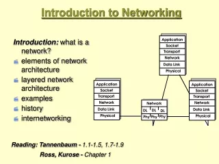
Introduction to Data Networking. ELEG 651. Introduction to This Class. Instructor: Stephan Bohacek bohacek@udel.edu, 302-831-4274 http://www.eecis.udel.edu/~bohacek Textbook: Kurose and Ross: Computer Networks (4 th or 5 th edition?) Web page has syllabus class notes

E N D
Introduction to Data Networking ELEG 651
Introduction to This Class • Instructor: Stephan Bohacek • bohacek@udel.edu, 302-831-4274 • http://www.eecis.udel.edu/~bohacek • Textbook: Kurose and Ross: Computer Networks (4th or 5th edition?) • Web page has • syllabus • class notes • videos lectures of some topics (in progress) • homework assignments • project assignments • announcements • Issues • Meeting time M+W 2-3:30 or 2:30-4? • Programming languages: C++ or java? • Computers: • >=2GB ram? • Windows or Linux?
The Internet • What is the longest time that you have gone without using “the Internet?” • What is the Internet? • How do you use the Internet? • Do you only watch TV over the Internet, or do you have cable? • Skype? • Facebook? • IM? • Twitter? • Smart phone? • Do you only have a data plan on your phone?
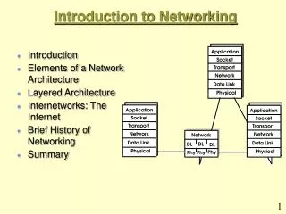
Today – networking basics • Core components of the Internet – the protocol stack • Multiplexing, circuit switching, and packet switching • Loss and delays • The structure of the Internet • This lecture covers much of chapter 1 in the textbook.
Today – networking basics • Core components of the Internet – the protocol stack • Multiplexing, circuit switching, and packet switching • Loss and delays • The structure of the Internet • This lecture covers much of chapter 1 in the textbook.
Core components • End-hosts • Applications • ? • Packets • TCP • UDP • Routers and gateways and groups of routers (ISPs) • Links • ? • Protocols
Core components • End-hosts • Applications • Web • Email • File transfer • File sharing • Packets • TCP • UDP • Routers and gateways and groups of routers (ISPs) • Links • Fiber • Coaxial • Twisted pair • Wireless • Protocols
Application Layer – where the applications live Email: Rules/protocols for how an end-host gets mail from the mail server Web: Rules/protocols for how the end-hosts gets a web page from the web servers Question: How is a networking application different from a non-networking application (e.g., MS Word). That is, why do we say that an application is a bunch of rules? MS-Word is not a bunch of rules? Answer: The networking applications must communicate, and rules are required to define the communication. Roles that end-hosts play: Client, server, and peer The client asks the server for a service. E.g., The client asks the server to send a mail for it. The client asks the server for a web page The client asks the server to translate a web address to an IP address. Peer: A host can act as both a client and a server. But usually in one transaction, the host takes only one role • End-hosts • Applications • Web • Email • File transfer • File sharing • Packets • TCP • UDP • Routers and gateways and groups of routers (ISPs) • Links • Fiber • Coaxial • Twisted pair • Wireless • Protocols
Layers 2-4 • End-hosts • Applications • Web • Email • File transfer • File sharing • Packets • TCP • UDP • Routers and gateways and groups of routers (ISPs) • Links • Fiber • Coaxial • Twisted pair • Wireless • Protocols Which are the end-host? client server Routers
Layers 2-4 • Why is this a good approach? • Small problems are easier • to understand/solve. • 2.Different solutions can be • mixed and matched Goal: move messages from server to the client Approach: break the problem into little pieces. Each piece is a layer in the “protocol stack” • End-hosts • Applications • Web • Email • File transfer • File sharing • Packets • TCP • UDP • Routers and gateways and groups of routers (ISPs) • Links • Fiber • Coaxial • Twisted pair • Wireless • Protocols client server
Layers 2-4 client server • End-hosts • Applications • Web • Email • File transfer • File sharing • Packets • TCP • UDP • Routers and gateways and groups of routers (ISPs) • Links • Fiber • Coaxial • Twisted pair • Wireless • Protocols • Top down approach of breaking problems into small pieces • Transport layer • Reliability: The server must make sure that the client gets the data • Congestion control (or lack there of) • Congestion Control: The server should send data as fast as possible, but not too fast • TCP provides these features (services), while UDP does not • Network layer (could be called the routing layer, but it isn’t) • The packets must find their way through the network. • Each packet has the IP address of the destination • By examining the IP address, routers decide where to send the packet next • Link Layer or MAC layer (link layer and MAC layer) • Links connect the routers/gateways and end-hosts • This layer provides logical and control for communicating across links. • Services that this layer might provide include • congestion control, media access, error detection/correction
Layers 2-4 • End-hosts • Applications • Web • Email • File transfer • File sharing • Packets • TCP • UDP • Routers and gateways and groups of routers (ISPs) • Links • Fiber • Coaxial • Twisted pair • Wireless • Protocols • Top down approach of breaking problems into small pieces • ….. • Link Layer or MAC layer (link layer and MAC layer) • Links connect the routers/gateways and end-hosts • This layer provides logical and control for communicating across links. • Services that this layer might provide include congestion control, media access, error detection/correction • Media access. The “air” is a shared medium. If two nodes transmit at the same time, there will be a collision. Thus, a scheme must be developed to determine which node transmits when. • Error detection/correction. If interference does occur, then errors might occur. If an error is detected, then • the error could be corrected with forward error correction, or • the receiving link could request a retransmission
Layers 2-4 client server • End-hosts • Applications • Web • Email • File transfer • File sharing • Packets • TCP • UDP • Routers and gateways and groups of routers (ISPs) • Links • Fiber • Coaxial • Twisted pair • Wireless • Protocols • Top down approach of breaking problems into small pieces • Transport layer • Reliability: The server must make sure that the client gets the data • Congestion control (or lack there of) • Congestion Control: The server should send data as fast as possible, but not too fast • TCP provides these features (services), while UDP does not • Network layer (could be called the routing layer, but it isn’t) • The packets must find their way through the network. • Each packet has the IP address of the destination • By examining the IP address, routers decide where to send the packet next • Link Layer or MAC layer • Links connect the routers/gateways and end-hosts • This layer provides logical and control for communicating across links. • Services that this layer might provide include • congestion control, media access, error detection/correction • Physical layer • Logical bits are encoded as physical quantities, e.g., as voltage levels, as shifts in phase, … • This course does not cover the physical layer
Protocols TCP connection response Get http://www.awl.com/kurose-ross <file> time • End-hosts • Applications • Web • Email • File transfer • File sharing • Packets • TCP • UDP • Routers and gateways and groups of routers (ISPs) • Links • Fiber • Coaxial • Twisted pair • Wireless • Protocols protocols define format, order of msgs sent and received among network entities, and actions taken on msg transmission, receipt Hi TCP connection request Hi Got the time? 2:00
Internet protocol stack application: supporting network applications FTP, SMTP, HTTP transport: process-process data transfer TCP, UDP network: routing of datagrams from source to destination IP, routing protocols link: data transfer between neighboring network elements PPP, Ethernet physical: bits “on the wire” application transport network link physical
ISO/OSI reference model presentation: allow applications to interpret meaning of data, e.g., encryption, compression, machine-specific conventions session: synchronization, checkpointing, recovery of data exchange Internet stack “missing” these layers! these services, if needed, must be implemented in application needed? application presentation session transport network link physical
Today – networking basics • Movie on the history of the Internet • Core components of the Internet – the protocol stack • Multiplexing, circuit switching, and packet switching • Loss and delays • The structure of the Internet • This lecture covers much of chapter 1 in the textbook.
Circuit switching versus Packet switching • Packet switching brought the networking revolution • Circuit switching • Virtual circuit networking • A half-way point between packet switched and circuit switched networking
Circuit switching • Circuit switching • Old style phone system • Each connection gets its own wire or bandwidth • Note: calls must be set-up. • E.g., • Me: operator, get my the president. • Operator: one moment please. • Then she plugs a cable into a socket so now I have a physical wired between me and the president. • Instead of each connection getting a whole wire, connections can share a wire via multiplexing • The first automatic circuit switching was developed by Almon Strowger – an undertaker. There were two undertakers in a small town and the switch board operator was the wife of the other undertaker. So Strowger invented an automatic circuit switch to rid both husband and wife of employment.
Frequency division multiplexing phone End office 300 100300 200300 300 3400 103400 203400 3400 On each hop, the connection gets its own bandwidth toll office End office phone • Frequency division multiplexing is used in • TV & radio • Cell phones (not so much today)
Time division multiplexing There are standard bit-rates that support multiplexing different numbers of calls Multiplex 28 DS1 = 28*24*64kbps + overhead = 44.736Mbps DS-3 1 1 1 2 Multiplexing 810 channels + overhead = 51.84 = STS-1/OC-1 STS is electrical and oc is optical OC3 = 155.52Mbps (150.336 payload) OC12 = 633.08 Mbps (601.344 payload) OC48 = 2.488Gbps (2.405Gbps) OC192 = 9.953Gbps (9.6Gbps payload) Multiplex 24 channels = 24*64kbps + overhead = 1.544Mbps DS1 (T1) 64kbits 1 2 3 bytes Overhead is 1 bit per 8*24 bits = 8000bps 1/8000 sec per byte 7 bits of data and one bit for control (data or not), so it really 56kbps of data • Note all the control overhead: if the bit is 1, then payload is control. • Lots of control is needed to setup a circuit. How is it possible to get channels at each hop? • Also, if there is not data, then nothing is sent. This wastes data. • But the circuit is yours, guaranteed!
Packet switching - Statistical multiplexing Packet format specification specifies where the address is data 1 client Server: address = 1 • Data is in packets, not streams. • Must be digital • Each packet has an address • A switch/router reads the whole packet, then reads the address and forwards the packet – store and forward
Packet switching - Statistical multiplexing data data data data 1 1 1 1 • Data is in packets, not streams. • Must be digital • Each packet has an address • A switch/router reads the whole packet, then reads the address and forwards the packet – store and forward If destination is 1, then next hop is C If destination is 1, then next hop is B B If destination is 1, then next hop is A C D client Server: address = 1 F E
Packet switching - Statistical multiplexing • Data is in packets, not streams. • Must be digital • Each packet has an address • A switch/router reads the whole packet, then reads the address and forwards the packet – store and forward • No reservations are needed. First come first serve. • Major benefit: • If you need more bandwidth, then you can get it, it you don’t need it, then maybe someone else can use it. • Major drawback: • What happens if two packets arrive at a switch and both need to go to the same output interface. Picture. One packet is either dropped, or is placed in a buffer. Either way, something bad has happened, the packet is gone, or is delayed. This would never happen on a circuit switched network. queuing delay and packet loss
Packet vs. Circuit Switching If usage is random (e.g., web surfing) statistical multiplexing is better. Suppose that • A 5Mbps link • Each user needs 50kbps • And each user is active 20% of the time. (note that this condition does not matter for circuit switching. Why?) How many users can be accommodated under packet switching and how many can be accommodated under packet switching? Circuit switching case The total number of users that can be accommodated with circuit switching is 5e6/50e3 = 100 users
Packet Switching Case Is the number of ways that you can select k out of n This is called the Binomial distribution Now if there are 200 users, what is the probability that there are 150 or more active users? In this case, there would be a problem, since the network cannot support more than 100 active users. Simpler questions: What is the probability of 150 particular users being active and 50 other being inactive? How many different ways can I select these 150 active users? Is the number of ways that you can select 150 people out of 200 The probability of any 150 users being active and the rest in active is
Packet Switching Case This is the binomial complimentary cumulative distribution Still pretty good What is the probability of more than 100 users being active? The probability of 101 users being active plus, 102 users being active, plus, …., 200 users being active, which is We conclude that if there are 200 users, then in “pretty much always” things will work fine Suppose that there are 300 users: Might be acceptable performance Suppose that there are 400 users: Therefore: circuit switching could support 100 users, while packet switching can support 400 users. A factor of 4 more!!!
Packet Switching vs. Circuit Switching What does this probability really mean? A couple of things: • This means that • when you walk into the switching center, the probability of finding overload is 10^-8. • Or, if you random access the link, the probability of finding it in overload. • Once you find it in overload, or not, the probability that is will be in overload in the next second is more complicated and requires queuing theory. This analysis might reveal worst performance. • In this example, we assumed 20% user utilization (they were active 20% of the time) • Is this large or small? • If it the user utilization is smaller, then the difference between packet switching and circuit switching is even larger. But it is larger, then there is less of a difference. • What is your user utilization? • For web surfing • For cell phone usage • For music streaming • p2p
Packet Switching vs. Circuit Switching • If loss and delay are permissible and usage is random, then packet switching is better than circuit switching. • If usage is very regular (e.g. TV!), circuit switching is best. • If losses and delay are not permissible, then circuit switching is best (e.g., remote controlled surgery). • With packet switching, congestion control is required. Also, there is more overhead for each packet. • For circuit switching, once the circuit is setup, it can be very efficient. But circuits must be set-up. • So, for short file transfer, packet switching is good but for long file transfers, circuit switching might be better. There is a subtle difference between packet switching and statistical multiplexing. Statistical multiplexing means to use the resource as needed. This leads to the performance improvements mentioned but also the complications (delay and loss). The phone network uses circuit switching, but the circuits are statistically multiplexed between users. In packet switching, links are statistically multiplexed.
Packet Switching: Statistical Multiplexing Sequence of A & B packets does not have fixed pattern, bandwidth shared on demand statistical multiplexing. TDM: each host gets same slot in revolving TDM frame. D E 100 Mb/s Ethernet C A statistical multiplexing 1.5 Mb/s B queue of packets waiting for output link
Packet-switching: store-and-forward takes L/R seconds to transmit (push out) packet of L bits on to link at R bps store and forward: entire packet must arrive at router before it can be transmitted on next link delay = 3L/R (assuming zero propagation delay) Example: L = 7.5 Mbits R = 1.5 Mbps transmission delay = 15 sec L R R R more on delay shortly …
Today – networking basics • Movie on the history of the Internet • Core components of the Internet – the protocol stack • Multiplexing, circuit switching, and packet switching • Loss and delays • The structure of the Internet • This lecture covers much of chapter 1 in the textbook.
Losses and delay in packet switched networks A B packet being transmitted (delay) packets queueing (delay) free (available) buffers: arriving packets dropped (loss) if no free buffers • Losses • Transmission losses • In fiber links, bit-error is 10^-12 or better (i.e., less). • What is the probability of packet error when there are 1400 bytes in a packet? • In wireless links, the bit-error rate can be very high • Congestion losses. • If too many packets arrive at the same time, then the buffers will fill up and packets are lost. • Increasing the link speeds or reducing the number of users can reduce the probability of loss. • Increasing the size of the buffer reduces losses, but also increases delay. • Delay • Queuing delay • Transmission delay • Propagation delay • Processing delay
Queuing delay A B packet being transmitted (delay) packets queueing (delay) free (available) buffers: arriving packets dropped (loss) if no free buffers • Queuing delay occurs for the same reason as congestion losses. • The more the network is utilized, the high the queueing delay (and losses) • Utilization = := actual use / maximum possible use • Suppose that • the link bit-rate is Z, • there are X users • Each users uses data rate Y, with probability P, and use no bandwidth with probability 1-p. = X*P/Z
Queuing delay Is it possible to have a network run at full utilization? No! The average delay would be infinite! From queuing theory Delay = /(1- )
Delay in packet switched networks 1400 *8 bits / packet = .0011 sec = 1.1 ms 10*10^6 bits / sec • Delay • Queuing delay • Transmission delay • Propagation delay • Processing delay How long does it take to transmit a packet? How long does it take to get all the bits from node on to the wire/air/fiber? • Suppose • Link bit rate is 10 Mbps • Packet size is 1400 bytes • How long to transmit the packet?
Delay in packet switched networks • Delay • Queuing delay • Transmission delay • Propagation delay • Processing delay How long does it take for a bit to travel along a wire/fiber/through the air? • Suppose • Speed of light in a vacuum 3e8 m/s while in a fiber it is 2e8m/s • How long does it take to transmit a bit from NY to LA = 3962km • 20ms propagation delay • How about from NY to Jakarta, Indonesia = 16,179km • 80ms • How about to a Geostationary satellite? • 250-300 (up and back) • Medium orbit satellites (e.g., GPS) • 120ms • Low-earth orbit satellites (low earth? What about middle-earth?) • Iridium at 10ms • Note, Iridium paid 5 billion for the network and sold for 25million (1/2%->on sale 99.5% off, everything must go) • Teledesic. 10ms
Fun with Propagation Delay How long is a bit? Suppose that a links transmits at 10mbps. How long is a bit? How long does it take to a bit? 1/10*10^6 = 10^-7 How far does the electric signal go in 10^7 sec? 10^-7 * 2e8 = 20 meters. How long many bits fit in a fiber at 10Mbps from NY to Jakarta? 16,179km*10^3/20 = 0.1 MB How long many bits fit in a fiber at 10 Gbps from NY to Jakarta? 16,179km*10^3/20 = 100 MB Satellite transmissions are subject to transmission loss (e.g., rain can cause interference), The satellite sending station could wait for and ACK from the other side and resend the data if no ACK appeared (a link layer solution) But this would cause out-of-order delivery So the satellite could hold the packets until the lost one is retransmitted. How large would the buffer need to be if the bit rate was 3Gbps? Answer .5*3e9/8=187MB (assuming no processor delay)
Delay in packet switched networks • Delay • Queuing delay • Transmission delay • Propagation delay • Processing delay Routers take a bit of time to process packets. • moving packets inside the router • Finding which is the next hop • Applying security or QoS
How to measure delay? • Ping: > ping 216.109.124.73 • Ping gives help • (linux) Ping –I 10 216.109.124.73 > file.txt • Then read it in excel and plot delay • Traceroute (linux), tracert (windows) • Traceroute 216.109.124.73 gives the routers and an estimate of the delay to each router.
Today – networking basics • Movie on the history of the Internet • Core components of the Internet – the protocol stack • Multiplexing, circuit switching, and packet switching • Loss and delays • The structure of the Internet • This lecture covers much of chapter 1 in the textbook.
Internet structure: network of networks roughly hierarchical at center: “tier-1” ISPs (e.g., Verizon, Sprint, AT&T, Cable and Wireless), national/international coverage treat each other as equals Tier-1 providers interconnect (peer) privately Tier 1 ISP Tier 1 ISP Tier 1 ISP
Tier-1 ISP: e.g., Sprint POP: point-of-presence to/from backbone peering … …. … … … to/from customers
Internet structure: network of networks “Tier-2” ISPs: smaller (often regional) ISPs Connect to one or more tier-1 ISPs, possibly other tier-2 ISPs Tier-2 ISPs also peer privately with each other. • Tier-2 ISP pays tier-1 ISP for connectivity to rest of Internet • tier-2 ISP is customer of tier-1 provider Tier-2 ISP Tier-2 ISP Tier-2 ISP Tier-2 ISP Tier-2 ISP Tier 1 ISP Tier 1 ISP Tier 1 ISP
Internet structure: network of networks “Tier-3” ISPs and local ISPs last hop (“access”) network (closest to end systems) Tier 3 ISP local ISP local ISP local ISP local ISP local ISP local ISP local ISP local ISP Local and tier- 3 ISPs are customers of higher tier ISPs connecting them to rest of Internet Tier-2 ISP Tier-2 ISP Tier-2 ISP Tier-2 ISP Tier-2 ISP Tier 1 ISP Tier 1 ISP Tier 1 ISP
Internet structure: network of networks a packet passes through many networks! Tier 3 ISP local ISP local ISP local ISP local ISP local ISP local ISP local ISP local ISP Tier-2 ISP Tier-2 ISP Tier-2 ISP Tier-2 ISP Tier-2 ISP Tier 1 ISP Tier 1 ISP Tier 1 ISP
ISPs and the structure of the Internet • Video of a Network Access Point (NAP) in Los Angeles
MEET ME ROOM Said to be the most interconnected space in the world and the most expensive real estate in North America, the “Meet Me Room” (a telco industry term) is the heart of One Wilshire. Here the primary fiber optic cables are routed, split, and shared. Because of the presence of so many telcos in this room and the ability to freely interconnect between them, rackspace here becomes extremely valuable. For comparison, the average price for office space in downtown Los Angeles is $1.75 per square foot per month. At the Meet Me Room, $250 per square foot would be a bargain.
CABLE RISERS Some 1,800 known conduits contain the fiber optic cables that flow through the building’s stairwells and vertical utility corridors, called “risers.” Cable connects the commercial telco tenants on floors 5 through 29 to the 4th floor Meet Me Room, and to a new, “wireless” Meet Me Room constructed on the 30th floor.
SURFACE CABLE MAP Whenever a permit is pulled by a city contractor for any underground repairs outside One Wilshire, the various telco companies with cable in the area come out and paint the cable routes on the asphalt, creating a visible graphic of the complexity of what lies just under the surface.