Download
1 / 18
180 likes | 280 Views
Coil Day 9:15 am , Wednesday, August 28 th , 2013 140 Cory Hall, Newest Instructional Lab, EECS Dept. UC Berkeley. What Coil Day Will/Won’t Cover. Will. Won’t. C13 receive arrays for small animals at 3 T Sample-noise dominance vs. coil-noise dominance

E N D
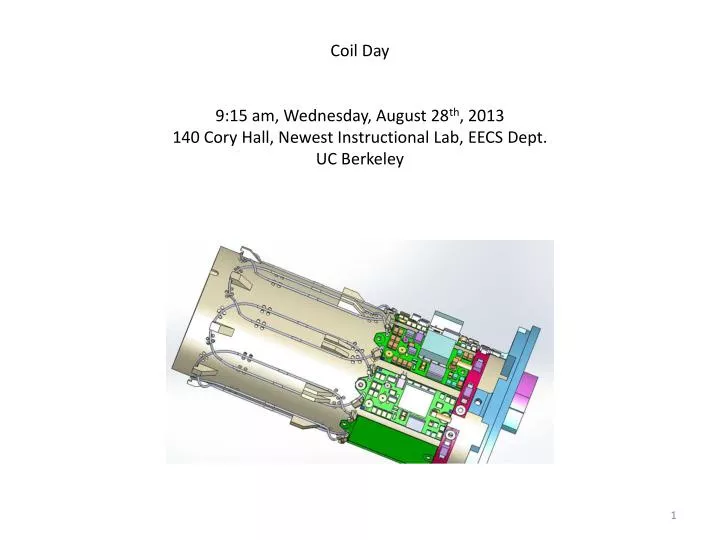
Coil Day 9:15 am, Wednesday, August 28th, 2013 140 Cory Hall, Newest Instructional Lab, EECS Dept. UC Berkeley
What Coil Day Will/Won’t Cover Will Won’t • C13 receive arrays for small animals at 3 T • Sample-noise dominance vs. coil-noise dominance • Comparisons/contrasts to proton surface coils • Proton traps • Tuning and matching • C13 preamps • Q-spoiling • Array Decoupling • Cables and cable traps • Building skills and testing techniques not in the literature • Volume coils (body coils) • Birdcage coils • Double-tuned coils • Transmit coils
A Few References D.I. Hoult and R.E. Richards, The signal-to-noise ratio of the nuclear magnetic resonance experiment, Journal of Magnetic Resonance, Vol. 24, pp. 71-85, 1976. D.I. Hoult, The NMR receiver: A description and analysis of design, Progress in NMR Spectroscopy, Vol. 12, pp. 41-77, 1978. P.B. Roemer, W.A. Edelstein, C.E. Hayes, et al., The NMR phased array, Magnetic Resonance in Medicine, Vol. 16, pp. 192-225, 1990. P.J. Fish, Electronic noise and low noise design, Macmillan, 1993. G. Scott, Build your own receiver coils, personal notes, Stanford University, 1997. J.H. Ardenkjaer-Larsen, B. Fidlund, A.Gram, et al., Increase in signal-to-noise ratio of >10,000 times in liquid-state NMR, Proceedings of the National Academy of Sciences, USA, Vol. 100, pp. 10158-10163, 2003. L. Darasse and J.C. Ginefri, Perspectives with cryogenic RF probes in biomedical MRI, Biochimie, Vol. 85, pp. 915-937, 2003. J. Mispelter, M. Lupu and A. Briguet, NMR probeheads for biophysical and biomedical experiments, Imperial College Press, 2006. F.D. Doty, G. Entzminger, J. Kulkarni, K. Pamarthy and J. P. Staab, Radio frequency coil technology for small-animal MRI, NMR Biomed., Vol. 20, pp. 304-325, 2007. J-X. Wang, N. Tian, F.J. Robb, A.P. Chen, L. Friesen-Waldner, B.K. Rutt and C.A. McKenzie, An 8-channel coil array for small animal 13C MR imaging, ISMRM, 2010. J. Tropp, J.M. Lupo, A. Chen, et al., Multi-channel metabolic imaging, with SENSE reconstruction, of hyperpolarized [1-(13)C] pyruvate in a live rat at 3.0 Tesla on a clinical MR scanner, Journal of Magnetic Resonance, Vol. 208, pp. 171-177, 2011. J.T Vaugh and J.R. Griffiths, eds., RF coils for MRI, John Wiley and Sons, 2012. J.P. Dunsmore, Handbook of microwave component measurements with advanced VNA techniques, John Wiley and Sons, 2012. B. Keil, Construction of receive arrays, ISMRM, 2013.
Revealing Cancer Metabolism w/C13 Imaging Pyruvic acid metabolizes into lactate & alanine differently in tumors, compared to normal tissue: Pyruvate Lactate Alanine The sign of pyruvate/lactate flips. Figue 4 from M.J. Albers et al., Cancer Research, 2008 (Kurhanewicz Group, UCSF).
Figue 2 from M.J. Albers et al., Cancer Research, 2008 (Kurhanewicz Group, UCSF).
Rat birdcage coil: normal rat injected with hyperpolarized urea . Thiis makes it possible to image the urea filtrate in the kidneys. This has potential use as a non-toxic perfusion measurement (at present, the only alternative involves nuclear medicine scans, but many patients with congenital kidney problem are children, who we wouldn’t want to expose to radiation). C13 image (from double-tuned tx-rcv birdcage coil) The colorized C13 image is overlaid on an H1 anatomy image, also acquired w/the birdcage coil. Images courtesy Galen Reed, Vigneron Group, UCSF Mission Bay 3 T scanner
Recent results: tagging hyperpolarized urea with N15 and exploiting long T2 C13 image Colorized C13 image overlaid on H1 anatomy image Images courtesy Galen Reed, Vigneron Group, UCSF Mission Bay 3 T scanner
C13 Parallel Imaging Anesthetized rat in two 4-ch C13 paddle coils Tail-vein catheter for injection of hyperpolarized pyruvic acid (C13) Images courtesy Peter Shin, Vigneron Group, UCSF Mission Bay 3 T scanner
C13 images from each of the 8 coils in the two paddles: Ch 1 Ch 2 Ch 3 Ch 4 Ch 5 Ch 6 Ch 7 Ch 8 SSoS Note: these two 4-ch paddle arrays were designed for human liver and brain imaging. It would be nice to have smaller, animal-dedicated, phased array coils – for better sensitivity. Images courtesy Peter Shin, Vigneron Group, UCSF Mission Bay 3 T scanner
Small vial (made out of PEEK plastic) for pyruvic acid and/or urea. If both are polarized together, the urea is put in the vial first, then the vial is dunked in liquid nitrogen and frozen, then the pyruvic acid is added on top of the frozen urea. They are frozen separately to prevent mixing. Then the vial is put in the hyperpolarizer for 2 hours (3.35 Tesla, 1.3 oK). The pyruvic acid is mixed with Trityl, and pipetted into the vial: Hyperpolarizer (GE Spin Lab) Photos: UCSF Mission Bay
After the pyruvic acid and/or urea is dissolved and removed from the hyperpolarizer, the spins only stay aligned for ~1 minute, so it’s immediately injected into a rat or mouse and imaged. These are two commonly used birdcage coils at UCSF Mission Bay. The rat’s nose sticks out this end and is cupped with this anesthesia hose: Double-tuned, C13 & H1, birdcage rat coil (tx & rcv for C13 & H1) Double-tuned, C13 & H1, birdcage mouse coil (tx & rcv for C13 & H1) Photos: UCSF Mission Bay
For parallel imaging on a human subject, these two 4-channel paddle-shaped C13 receive-only arrays are available. The paddles must be used with a C13 transmitter such as this clamshell-shaped one (in Helmholtz coil configuration): GE designer: Dr. James Tropp J Magn Reson. 2011 January; 208(1): 171-177. Photos: UCSF Mission Bay
GE 8-channel C13 rat coil (from ISMRM 2010 abstract) Eight C13 preamps Inner cylinder: 8-ch C13 receive array, around the circumference of the cylinder Outer cylinder: Birdcage C13 transmitter
Inner cylinder: 8-ch C13 receive array, around the circumference of the cylinder Hard to see in this photo, but we’d like to have a copy of this 8-ch C13 receive array, as it would be useful to a number of UCSF researchers. For parallel imaging acceleration, we like the geometrical configuration of having the 8-channels wrapped around the circumference of a cylinder.
For Coil Day, we’re going to build a similar rat 8-ch C13 receive array, along with the associated preamps. For the C13 transmitter, we’ll be using the clamshell tx which already exists at UCSF Mission Bay. Our rat cylinder will go inside the clamshell and both will slide into the bore of the 3 T scanner (where the body coil is used for H1 anatomy images of the rat).
...still to do ... Sample-noise dominance vs. coil-noise dominance
Fill factor: metric regarding the geometric coincidence between the coil and the sample Fill factor’s original definition: measure of the fraction of the (solenoildal)coil volume occupied by the sample Fill factor = (Magnetic energy stored inside the sample volume)/(Total magnetic energy stored by the coil) ... and some more slides still to do...