
Understanding Chip Coordinates and Axis Orientation in JDF Files
This guide explores the concept of chip coordinates and axis orientation, specifically highlighting how the vertical axis is inverted in the chip coordinate system used in JDF files. It provides insights into viewing the chip from the back side, ideal for professionals in fields like chip design and manufacturing. By explaining the coordinate system and how it affects handling and viewing angles, this resource aims to clarify the processes involved and the proper interpretations of data.

Understanding Chip Coordinates and Axis Orientation in JDF Files
E N D
Presentation Transcript
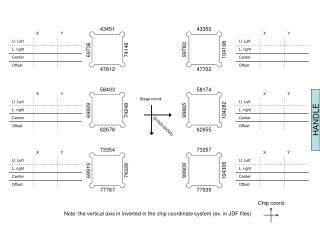
43451 43350 99780 69736 74146 104198 47812 47702 58403 58174 Stage coord. 99865 69828 74248 104282 (87000,60000) 62678 62655 73354 73257 99909 69919 74339 104306 77767 77539 Chip coord. Note: the vertical axis in inverted in the chip coordinate system (ex. in JDF files) HANDLE
HANDLE View from the back side