Download
1 / 35
370 likes | 539 Views
CIS 4365 Entity Relationship Diagrams. Chapter3 :. Entity-Relationship Modeling:. Part 1. CIS 4365 Entity Relationship Diagrams. The E ntity R elationship D iagram ( ERD ). • Developed by Chen (1976).

E N D
CIS 4365 Entity Relationship Diagrams Chapter3: Entity-Relationship Modeling: Part 1
CIS 4365 Entity Relationship Diagrams The Entity Relationship Diagram (ERD) • Developed by Chen (1976) • THE Most commonly used data modeling tool • Shows the structure, requirements and constraints of the intended system, independent of software (DBMS), at a higher level of abstraction • Tool for communications between database designers and users • Also used as a planning/organization tool
A Quick Aside: • How many times have you been shown a model in a class only to find out it is useless ?? Too Many !!! • This is NOT one of those times --- • ERDs form the foundation of all database modeling • It is IMPOSSIBLE to develop a working Database without them
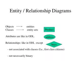
CIS 5365 Entity Relationship Diagrams Basic ERD Symbols • Anything about which we wish to maintain information Entity Person Thing Event Place Object Description • Entity Instance: A single occurrence of the entity (record) • Entity Type: A collection of entity instances • An association (or action which occurs) between Entity types Relationship Customersplaceorders Orderscontainparts • Fields within a Record (entity instance) Attributes CUSTOMER(custid, name, address) • Connectors between other elements
CIS 5365 Entity Relationship Diagrams A Simple ERD: Consider the following description: “A customer places an order. The order consists of parts.” Entity Relationship Another Relationship Orders Customer Places Contain An Association between Entities Another Entity Parts Someone whom we wish to keep information about
CIS 5365 Entity Relationship Diagrams Parts PROBLEM:The model does not clearly show how the entity instances are related (Cardinality) How many parts can one order contain? Places Contain 1 M M Customer Orders How many customers are associated with an order? How many orders can a customer place? M A One-to-Many (1:M) Relationship How many parts can be in one order? A Many-to-Many (M:M) Relationship
CIS 5365 Entity Relationship Diagrams Orders Parts Alternative Notation Given 1 Order, How many parts can it contain?? Many Contain Places Customer One Given 1 Customer, how many Orders can be placed ?? Given 1 Order how many cust- omers placed it? Many Many Given 1 part, How many orders can contain it ??
CIS 5365 Entity Relationship Diagrams Seat Degree of Relationship: Number of Entities Participating • Binary Relationships (degree 2): Thought to be most common Places 1 M Customer Orders a 1:M Binary Relationship Contain M M Orders a M:M Binary Relationship Parts Occupies 1 1 Student a 1:1 Binary Relationship
CIS 5365 Entity Relationship Diagrams Degree of Relationship: Number of Entities Participating • Other Relationships a 1:M Unary Relationship a M:M:M Ternary Relationship a M:M:M:M Relationship Degree Four More on these later
CIS 5365 Entity Relationship Diagrams Orders Parts Cardinality Constraints An Order MAY (OPTIONAL) contain many parts. Customer Places Contain An Order MUST (MANDATORY) be placed by one customer A Customer MAY (OPTIONAL), place more than 1 order. NOTE: While we will occasionally use Cardinality constraints (so that you can learn them) they will NOT be required in ERDs that you turn in A Part MUST (MANDATORY) be contained in many orders
CIS 5365 Entity Relationship Diagrams Orders Orders Additional Notation An Entity which is not dependent upon other entities Strong Entity Customer An Entity which exits only because of another entity Weak Entity Customer Places Identifying Relationship NOTE: Once again, we will occasionally use this notation (so that you can learn them) they will NOT be required in ERDs that you turn in
CIS 5365 Entity Relationship Diagrams Associating Attributes With Entities Simple Attribute Customer_Name Customer An attribute (field) that is functionally dependent upon the primary key: • Your name, address, GPA, and many other attributes (all simple attributes) are functionally dependent on your SSN/Student ID • If I know your SSN/Student ID, I know your name, address, and other simple information
CIS 5365 Entity Relationship Diagrams Associating Attributes With Entities Simple Attribute Derived Attribute Yrs_in_Business Customer_Name Customer • The number of years in business is not actually stored, but will be calculated when displayed • The date established (a numerical value) is stored and then subtracted from the present date (also a numerical value)
CIS 5365 Entity Relationship Diagrams Associating Attributes With Entities Simple Attribute Derived Attribute Yrs_in_Business Customer_Name Customer Customer_ID Primary Key • The unique identifier for each record
CIS 5365 Entity Relationship Diagrams Associating Attributes With Entities Simple Attribute Derived Attribute Yrs_in_Business Customer_Name Customer Customer_ID Employer Primary Key Foreign Key • A link to a unique identifier in a different table
CIS 5365 Entity Relationship Diagrams Associating Attributes With Entities Simple Attribute Derived Attribute Yrs_in_Business Customer_Name Customer Customer_ID Employer Primary Key Address Foreign Key Composite Attribute • An attribute which contains a fixed number of additional attributes, sometimes shortened as: State City Street Address
CIS 5365 Entity Relationship Diagrams Associating Attributes With Entities Simple Attribute Derived Attribute Yrs_in_Business Customer_Name Multivalued Attribute Customer Purch_Agts Customer_ID Employer Primary Key Address Foreign Key Composite Attribute What’s the difference between Multivalued and Composite Attributes?? State City Street
CIS 5365 Entity Relationship Diagrams Composite Attributes • Composite attributes have a fixed number of attributes associated with it Address • e.g. Street, City, State, Zipcode • They are often used in the initial design of a database because while the designer knows that there will be a fixed number, s/he might not be sure exactly what attributes will be included Sometimes drawn as: Address • e.g. Should we also include apartment number and country? State State City City Street Street
CIS 5365 Entity Relationship Diagrams Multivalued Attributes • Multivalued attributes have a Variable number of attributes associated with it • Assume you are a salesman. Your clients are of different sizes: • At a 7-11, you have one purchasing agent to deal with • At UTEP, you have twelve purchasing agent to deal with Purch_Agts • At Fort Bliss, you have forty-six purchasing agent to deal with • These are known as Repeating Groups, and will require refinement (more later)
CIS 5365 Entity Relationship Diagrams Yet Another Notation Method • There is one more we need to know about: UML (Unified Modeling Language) Set of OO modeling conventions that are used to specify or describe software systems Attempt to create a single, standard process Provides notation for OO Modeling • Does NOT prescribe a method for developing Systems Adopted by the Object Management Group as the industry standard in 1997 • Still often referred to as a ‘work in progress’
CIS 5365 Entity Relationship Diagrams Places Contain Customer Orders Parts 1 .. * * .. * • OrdID • ~CustID • CustID • Name • Street • City • State • Zipcode • PartID • x Others Yet Another Notation Method In UML, we might represent our relationship as: • Relationship Notation: • 1 One and only one • * Any number from 0 to infinity • 0..1 Either 0 or 1 • n..m Any number in the range n to m inclusive • 1..* Any positive integer • Attribute Notation: • • Primary Key • ~ Foreign Key • x Composite Attribute
CIS 5365 Entity Relationship Diagrams Additional Relationships • Consider the relationship between the Part that a Vendor (wholesaler) ships to a Store M Vendor M M Shipped to Parts A Vendor sells many Parts Sells The same Part can be sold by many Vendors A M:M Relationship M A Part can be shipped to many Stores Stores Stores can hold to many Parts Also a M:M Relationship
CIS 5365 Entity Relationship Diagrams Additional Relationships • Assume that the same Hammer is sold by six different Vendors M Vendor M M Shipped to Parts Sells • Assume that these Hammers may (or may not) be sent to any Home Depot stores in El Paso (let’s assume that there are 10 Home Depots in El Paso) M Stores Do we know what Hammer came from what Vendor???
CIS 5365 Entity Relationship Diagrams Additional Relationships • The three entities are interdependent (A simultaneous relationship) • Can a Vendor exist if there are no Parts to sell? • Can a Vendor exist if there are no Stores to sell their Parts to? • Can a Part exist if there are no Vendors to sell them? • Can a Store exist if there are no Parts? This is a TERNARY relationship (i.e., a relationship of degree three)
CIS 5365 Entity Relationship Diagrams How do we determine cardinality? Parts Vendor Store Supplies • Given 1 vendor and 1 part, how many Stores? Many Many • Given 1 Store and 1 vendor, how many parts? Many • Given 1 Store and 1 part, how many vendors? Hence a M:M:M ternary relationship
CIS 5365 Entity Relationship Diagrams What about cardinality constraints? Parts Vendor Store Supplies • Given 1 vendor and 1 part, MUST there be many Stores? NO • Given 1 Store and 1 vendor, MUST there be many parts? NO • Given 1 Store and 1 part, MUST there be many vendors? NO The TRUE solution lies in the actual situation
CIS 5365 Entity Relationship Diagrams Another Relationship • Suppose UTEP wished to track employees who were married to each other (e.g., for insurance purposes) • We could set up a binary relationship An Employee may have 1 spouse A Spouse CAN have ONLY 1 Employee Is Married to Employee Spouse Spouse SSN SSN Addr. SSN Addr. But, Each Entity Type has the same attributes
CIS 5365 Entity Relationship Diagrams Another Relationship • We could create a Unary relationship An Employee May be married Is Married to Employee A Spouse Must be married How would the tables in this relationship look like? Aren’t we duplicating too much data, like Addresses?
CIS 5365 Entity Relationship Diagrams Another Relationship • We could also create a Lookup Table Address Is Married to Employee • Where the tables would appear as: Table Employee Table Address Lives at The Question is: Should we??
CIS 5365 Entity Relationship Diagrams Another Relationship • That is a decision for the DBA, based on: • How many employees share a common address? (I don’t think there are too many UTEP employees who are married to each other – But what do I know!!!) • Unary relationships may take on any cardinality • 1:1 An Employeeis married to another Employee (In a Polygamist/Polyandrist society, this is a 1:M relationship) Don’t forget: It depends on what is actually taking place! • 1:M An Employeemanages many other Employees • M:M Parts contain other Parts (This relationship is a Recursive relationship)
CIS 5365 Entity Relationship Diagrams Another Relationship • Consider another example: “At this college, there are many departments. Each department has a number of faculty members, and a faculty member may belong to only one department. In each department, there is one faculty member assigned to supervise the other faculty members”. • Let’s build the ERD in stages • Keep in mind that there are many ways to arrive at the same solution (Equifinality)
CIS 5365 Entity Relationship Diagrams Faculty Another Relationship • We know that we have Departments which consist of Faculty • Both must be entity types, since we wish to keep information about them • We also know that Departments have many Faculty and that each Faculty may belong to a single Department Department Consists of Given 1 Department, how many faculty members? Many Given 1 Faculty member, how many departments? One
CIS 5365 Entity Relationship Diagrams Another Relationship • We also know that a Faculty member is designated as another Faculty member’s supervisor. • Our ERD might now appear as: Department Consists of Faculty Supervises One faculty member MUST supervise many other faculty members Each faculty member MUST be supervised by ONLY ONE other faculty member
CIS 5365 Entity Relationship Diagrams Another Relationship • We will need one additional relationship: “The faculty member who supervises other faculty is also responsible for managing the department” Department Consists of Faculty Supervises Manages Given 1 Department, how many faculty managers? One(and only one) Given 1 Faculty, how many Departs. does s/he manage? One(or none) How would the tables in this relationship look like?
CIS 5365 Entity Relationship Diagrams Another Relationship Faculty Department Consists of Faculty Supervises Department Manages