Download
1 / 29
290 likes | 357 Views
Computer Buses. A bus is a common electrical pathway between multiple devices. Can be internal to the CPU to transport data to and from the ALU. Can be external to the CPU, to connect it to memory or to I/O devices. Early PCs had a single external bus or system bus .

E N D
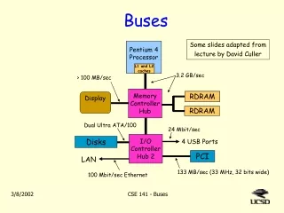
Computer Buses • A bus is a common electrical pathway between multiple devices. • Can be internal to the CPU to transport data to and from the ALU. • Can be external to the CPU, to connect it to memory or to I/O devices. • Early PCs had a single external bus or system bus. • Modern PCs have a special-purpose bus between the CPU and memory and (at least) one other bus for the I/O devices.
Computer Buses • In order to make it possible for boards designed by third parties to attach to the system bus, there must be well-defined rules about how the bus works, and which all attached devices must obey. • These rules are called the bus protocol. • In addition, there must be mechanical and electrical specifications.
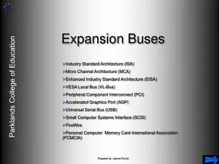
Computer Buses • A number of buses are in widespread use in the computer world. • Multibus (8086) • IBM PC (PC/XT) • ISA bus (PC/AT) • EISA bus (80386) • Microchannel (PS/2) • PCI bus (Many PCs) • Nubus (macintosh) • Universal Serial Bus (modern PCs) • FireWire (consumer electronics)
Computer Buses • Some devices that attach to a bus are active and can initiate bus transfers. They are called masters. • Some devices are passive and wait for requests. They are called slaves. • Some devices may act as slaves at some times and masters at others. • Memory can never be a master device.
Computer Buses • The binary signals that computer devices output are frequently not strong enough to power a chip. • The bus may be relatively long or have several devices attached to it. • Most bus masters are connected to the bus by a chip called a bus driver which is essentially a digital amplifier. • Most slaves are connected to the bus by a bus receiver.
Computer Buses • For devices which can be both master and slave, a device called a bus transceiver is used. • These bus interface devices are often tri-state devices to allow them to disconnect when they are not needed. • A bus has address, data, and control lines, but there is not necessarily a one-to-one mapping between CPU pins and bus lines. A decoder chip between CPU and bus would be needed in this case.
Bus Width • The more address lines a bus has, the more memory the CPU can address directly. • If a bus has n address lines, then the CPU can use it to address 2n different memory locations. • Larger buses are more expensive: • they need more wires • they take up more space on the motherboard • they need bigger connectors • Early PC buses did not contain enough address lines leading several backward compatible upgrades to the bus.
Bus Width • The number of data lines needed also tends to increase over time. • There are two ways to increase the data bandwidth of a bus: • decrease the bus cycle time • increase the data bus width • Speeding up the bus results in problems of bus skew since data on individual lines travel at slightly different speeds. This also makes the bus non-compatible with pre-existing devices.
Bus Width • Therefore, an increased data width is the usual answer (e.g. in the PC which went from 8 data lines to 16 and then to 32 on essentially the same bus). • Another solution is to use a multiplexed bus. • The same lines are used for both data and addressing by breaking up the bus operation into multiple steps. This slows down bus performance.
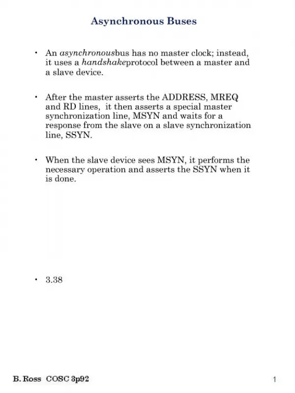
Bus Clocking • Buses can be divided up into two categories depending on their clocking. • A synchronous bus has a line driven by a crystal oscillator. • The signal on this line consists of a square wave with a frequency of 5 - 100 MHz. • All bus activities take an integral number of these cycles, called bus cycles. • The asynchronous bus does not have a master clock. Bus cycles can be of any length required and need not be the same.
Bus Clocking • Consider a synchronous bus with a 40-MHz clock, which gives a clock cycle of 25 nsec. • Assume reading from memory takes 40 nsec from the time the address is stable. • It takes three bus cycles to read a word. • MREQ’ indicates that memory is being accessed. RD’ is asserted for reads and negated for writes. WAIT’ inserts wait states (extra bus cycles) until the memory is finished
Bus Clocking • Although synchronous buses are easy to work with due to their discrete time intervals, they also have some problems. • Everything works in multiples of the bus clock. • If a CPU and memory can complete a transfer in 3.1 cycles they have to stretch it to 4.0 because fractional cycles are forbidden. • Once a bus cycle has been chosen, and memory and I/O cards have been built for it, it is difficult to take advantage of future improvements in technology. The bus has to be geared to the slowest devices (legacy devices) on the bus.
Bus Clocking • Mixed technology can be handled by going to an asynchronous bus. • The master device asserts MREQ’, RD’, etc. and then asserts MSYN’ (Master SYNchronization). • Seeing this, the slave device starts to work. • When it is finished it asserts SSYN’ (Slave SYNchronization). • Seeing this, the master reads the data. • When it is done, it negates MREQ’, RD’, the address lines, MSYN’ and SSYN’.
Bus Clocking • This ends the read. • A set of signals that interlocks in this way is called a full handshake. • Full handshakes are timing independent. Each event is caused by a prior event, not by a clock cycle. • Despite the advantages of asynchronous buses, most buses are synchronous since they are easier to build, and since there is such a large investment in synchronous bus technology.
Bus Arbitration • I/O chips have to become bus master to read and write memory and to cause interrupts. • If two or more devices want to become bus master at the same time, a bus arbitration mechanism is needed. • Arbitration mechanisms can be centralized or decentralized. A simple form of centralized arbitration is shown on the next slide. • When the arbiter sees that one or more devices want to become master, it issues a grant by asserting the bus grant line.
Bus Arbitration • In the first scheme shown, the closest device always wins. • In the second scheme, there are multiple levels of priority. A device assert the line for its priority, and the arbiter grants the request by asserting the line with the highest priority. • Since the CPU must compete for the device on most every cycle (i.e. it must read a word of memory) the memory is often put on a separate bus from the I/O devices so it doesn’t have to compete.
Bus Arbitration • Decentralized bus arbitration is also possible. • A computer could have 16 prioritized bus request lines. When a device wants to use the bus, it assert its request line. • All devices monitor all request lines, so at the end of each bus cycle, each device knows whether it was the highest priority requester. • This method avoids the necessity of an arbiter, but requires more bus lines. • Another decentralized scheme equivalent to the daisy chain arbitration minus the arbiter is shown on the following slide.
Bus Operations • Up until now, we have only considered ordinary bus cycles, with a master reading from a slave or writing to one. In fact, several other kinds of bus cycles exist. • Normally one word at a time is transferred. However, when caching is used it is often desirable to fetch an entire cache line at once. • Block transfers can often be more efficient than successive individual transfers. The master puts the number of words to be transferred on the data lines during the first bus cycle.
Bus Operations • Another important kind of bus cycle is for handling interrupts. When the CPU commands an I/O device to do something, it usually expects an interrupt when the work is done. The interrupt signaling requires the bus. • Since multiple devices may want to cause an interrupt simultaneously, the same kind or arbitration problems we had with ordinary bus cycles are present. • The usual solution is to assign priorities and use a centralized arbiter.
Bus Operations • Standard interrupt controller chips exist and are widely used. • The IBM PC and all its successors use the Intel 8259A chip. • Up to eight I/O controllers can be directly connected to the eight IR inputs to the 8259A. When one of these devices wants to cause an interrupt, it asserts its input line. • When one or more interrupts are asserted, the 8259A asserts INT which drives the interrupt pin on the CPU.
Bus Operations • When the CPU is able to handle the interrupt, it sends back a pulse on INTA. • At that point, the 8259A specifies which input caused the interrupt by outputting the input’s number on the data bus. • The CPU uses that number to index into a table of pointers called interrupt vectors, to find the address of the procedure to run to service the interrupt. • Several 8259As can be cascaded to handle more than eight I/O devices.