Download
1 / 31
310 likes | 344 Views
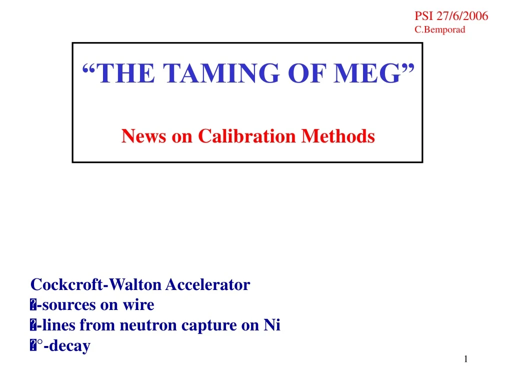
This news article discusses the calibration methods for the Cockcroft-Walton Accelerator in the MEG experiment, including the use of alpha sources on wire, gamma lines from neutron capture on Ni, and pi decay. It also highlights the importance of reliable and easy calibrations for the success of the MEG experiment.

E N D
PSI 27/6/2006 C.Bemporad “THE TAMING OF MEG” News on Calibration Methods Cockcroft-Walton Accelerator -sources on wire -lines from neutron capture on Ni °-decay
THE MEG EXPERIMENT COCKCROFT-WALTON ACCELERATOR & PROTON BEAM-LINE DELIVERY OF THE COCKCROFT-WALTON ACCELERATOR DEFINITION OF THE PROTON BEAM LINE BELLOWS SYSTEM FOR THE TARGET INSERTION INTO COBRA REQUEST FOR SPACE BEHIND THE MEG AREA FINANCING ETC.
POINTS TO BE CONSIDERED • The C-W accelerator is delivered on June-July 2007, after the start of the MEG data taking • The installation of the C-W accelerator at PSI and the C-W tuning requires at least one month • The C-W accelerator installation should not interfere with the MEG running • From time to time, some interventions and repairs on the C-W will be needed • The mutual effects between the C-W accelerator and the COBRA magnet must be small. Keep an adequate distance between them. • A large amount of space is needed (and available) in the MEG area for the bellows system and for the p-beam optical elements • It is convenient that the turning on and the tuning of the C-W accelerator take place while the MEG experiment is in normal running
CONSEQUENCES • Need for space at the back of the MEG area for the accelerator installation “Radiation Safety” independently surveyed area • Bellows system for p-beam and Li target introduction into COBRA • p-beam opposite to the -beam and on the same line (simpler !) • C-W accelerator at 7 m from the COBRA centre Optical elements needed for beam focusing and centring (4 steering magnets, 2 quadrupoles) The C-W accelerator construction and the bellows system preparation depend on a decision on the availability of the space downstream of the MEG area A RATHER COMPLEX PROJECT ! 1) MEG collaborative work 2) Help from the National Laboratories of Legnaro (advice and spare items) (Letter to/from and from the Lab. Director G.Puglierin) RELIABLE AND EASY CALIBRATIONS ARE ESSENTIAL TO MEG An earlier C-W installation translates into a saving in time, in effort, in money (The experiment can be tuned when the PSI beam is not allocated to MEG and during machine-off periods)
PROBLEMS WE ARE IMMEDIATELY FACING; URGENT SOLUTION NEEDED ! C-W accelerator in the engineering phase. Some characteristics depend on the accelerator position and hall space availability. Wait for a decision........? Delayed delivery ! The order and the construction of the bellows system depend on the C-W position. The cost of the bellows system is approx. 85.000 euro If immediately ordered, it could be ready by November 2006. Desirable a BVR positive recommendation about the use of hall space for the C-W installation during this June 27th meeting. Present INFN financial difficulties. Decision on our requests (To be based on hall space availability !) during the July 3rd, or successive Commission 1° September meeting
Cockroft-Walton Accelerator in a fixed position and Bellows system for inserting the p-beam and the LiF target into COBRA P-beam and target inserted into COBRA (not to scale) P-Beam and target out of COBRA
THE PRESENT MEG AREA The Bellows System and the p-beam optics (4 steering magnets and 1 quadrupole doublet) can be arranged in the MEG area
Present position of the shielding walls behind the MEG area AREA ON THE BACK OF MEG MEG AREA
Proposed position of the new shielding walls Behind the MEG area
Possibility of bellows system, beam optics, C-W accelerator installation in a single MEG area (not advisable.......)
SINGLETRON COCKCROFT-WALTON ACCELERATOR
BELLOWS SYSTEM FOR THE INTRODUCTION OF THE PROTON BEAM AND OF THE LiF TARGET INTO COBRA • The bellows system project is ready (the beam section from the accelerator to the bellows system must be completed) • It is advisable that the bellows system be built during the summer 2006, be fully tested under vacuum and be tuned before the end of the year • Development of the safety system and of the computer controls • Improvements in the LiF target and holder. Cooling. Beam centring and beam current readings. Beam optics controls Avoid, if possibile, a time-overlap between the installation of the bellows system and the delivery, mounting, tuning of the C-W accelerator ESTIMATED COST OF THE BELLOWS SYSTEM 85 Keuro (if the beam optics elements and power supplies are all available at no cost)
microphoto of LiF TARGET very small p-beam irradiation cells of approx. 30 m intermediate p-beam irradiation
heavy irradiation at p-beam spot IMPROVE Lithium Fluoride TARGETS BETTER CARE OF TARGET COOLING AND GOLD PROTECTION
-sources on wire recent improvements
Polonium Wire-Sources RINGS IN LIQUID XENON PMT Q.E. Measurements Now in print on Nuclear Instruments & Methods Great if used in the bulk of any Liquid Detector !
Quantum efficiency determinations in Large Prototype CHECK OF PMT PROPERTIES IN THE FINAL CALORIMETER DURING THE EXPERIMENT Americium WIRE SOURCES 5 WIRES, 5 DOT-SOURCES PER WIRE Wire of 100 micron diameter Material: gold plated steel or tungsten Total length 150 cm Spacing of dot-sources 12.4 cm Linear dimension of dots 1-2 mm Activity 200 Bq per dot
first SORAD/ISOTOPE PRODUCTS AMERICIUM WIRE-SOURCES made by a thermocompression method Irregular rings, well simulated by the Monte Carlo Method…… !
EXTRA R&D BY SORAD New modified sources shipped to Pisa on June 18th Elimination of the wing and of its shadow
EXTRA R&D BY SORAD interesting new method: Thermocompression of an Am-source strip wound around the wire
thermal neutron capture on nickel and 9 MeV -line
Calorimeter monitoring by NEUTRONS AND NICKEL-LINE (Americium Source) “hourly calibration” large-prototype NaI NaI /E=2.5% PROBLEM: in the LXe the line is worse; larger background due to fast neutron reactions n2n, n1, n2, n3, …..
WAY-OFF: • reduce the neutron energy by use of a Californium source • better reject -particles from sources on wire • select thermal neutrons events by a delayed gate window ( 100 s) and a trigger from fission prompt ’s (lower rate) A “GENERATOR” OF 9 MEV ’s FROM NICKEL MUST BE READY IN TIME FOR THE FIRST MEG RUN present problems with status of large Sodium Iodide Detector
hydrogen target to be used inside COBRA (new test: JUST NOW in Pisa !)
“THE TAMING OF MEG” all proposed calibration methods were tested and most of them are up to expectations WE ARE READY…..